3 - 16
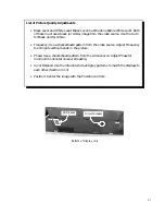
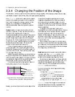
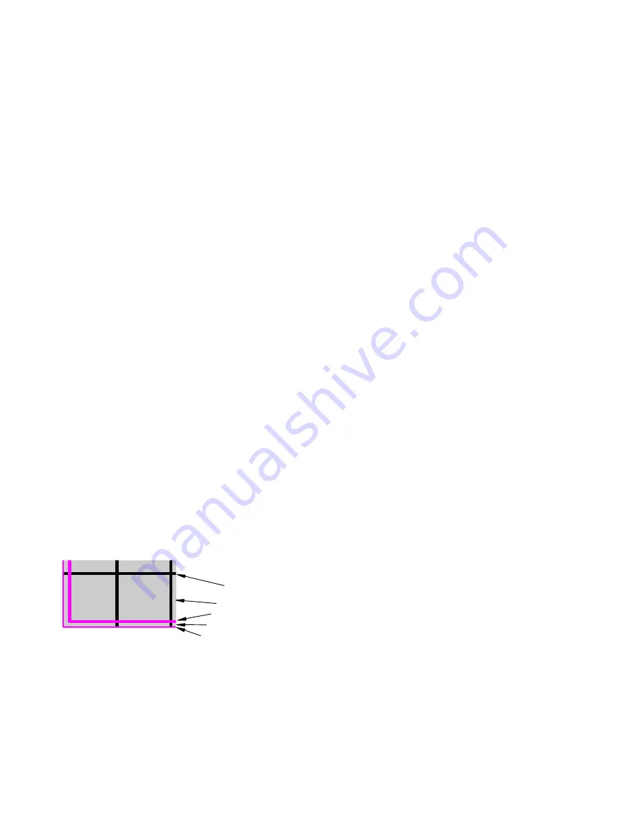
1 pixel magenta (hide)
2 pixels white (hide)
2 pixels magenta (see)
white background
2-pixel-wide
black grid
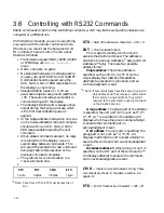
Lower left corner of internal Geometry test pattern
showing size and position of magenta lines
3.3 Adjusting for Optimum Picture Quality
3.3.4
Changing the Position of the Image
The Position control is used to move the electronic image slightly. If the display is black at any edge,
and Position doesn’t correct this, the unit needs optical adjusting.
The
Position
control will make minor adjust-
ments in the
electronic
position of the picture,
but it won’t change the optical position of the
picture. It is important to understand the
difference between these two types of position
control.
Optical
position means moving the LCD (for
up-down, right-left, or tilt), the lens (for size) or
the mirror (for keystoning). These are
mechanical adjustments you make if the picture
is keystoned, or tilted, or if the one edge of the
picture image leaves a dark line at the edge of
the screen. Or if the image doesn’t fill the screen
or fills it too much. Optical positioning moves
the bright area of the screen. Of course, the
picture in the bright area moves, too.
Think of optical positioning as moving a
cinema projector. Moving the projector moves
the bright image around on the white screen. If
you move it too much, there will be a dark area
on one edge of the screen.
Before you adjust anything, you should know
the goal of alignment and understand the parts
of the Geometry test pattern. The goal is to have
a rectangular image with three pixels hidden
behind each mullion (each screen border).
The internal Geometry test pattern helps in
hiding three pixels. Here is the pattern:
Ideally, you should just see the outer edge of the
2-pixel-wide magenta rectangle; the 1-pixel
magenta rectangle and the next two pixels of
white should be completely hidden. As with
most ideal situations, this is difficult to achieve
precisely. If you come within ±2 pixels of this
ideal, be satisfied.
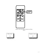
To adjust LCD alignment, press
MENU
.
Highlight Misc Control and press Enter. Choose
Test Patterns, then choose Geometry. Adjust
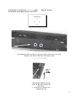
the LCD alignment with two screws at the
bottom of the display. These move the LCD up
and down and rotate it. Inside the air intake
door, you can find the horizontal adjustment
screw for the LCD.
If the image is too large or too small, rotate
the lens. You can reach the lens by opening the
air intake door and reaching up and back toward
the center of the unit. Rotating the lens changes
the image size, not the focus.
Electronic
position means moving left-right or
up-down with the
Position
control. The
image moves within the bright area of the
screen, but the bright area does not move.
If your banner application will have pictures
that span across two or more display units, it is
important that adjacent parts of the picture
match correctly. Minor adjustments with the
Position
control will do this.
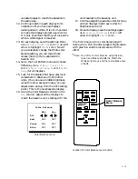
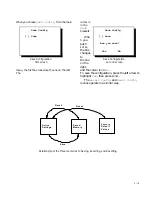
To move or position the image electronically,
follow these steps:
1. Open the
Position
menu (
MENU
>
Position
>
ENTER
.)
2. Highlight
Position
and press
ENTER
.
3. In the
Position
menu, use the four
arrow buttons to move the image.
4. Press
PREV MENU
twice to exit
Position
.
Position
moves the image in increments of
one pixel each time an arrow is pressed. You
can press and hold an arrow key to move
Summary of Contents for Leopard VN-3820-VA
Page 1: ...Leopard VN 3820 VA User Guide ...
Page 2: ......
Page 3: ...VN 3820 VA VN 3830 VA User s Guide 070 0032 06 7 October 2003 ...
Page 8: ...vi vi ...
Page 14: ...1 6 ...
Page 28: ...2 14 ...
Page 52: ...3 24 ...
Page 57: ...4 5 Don t spray liquids directly onto the face of the screen ...
Page 58: ...4 6 ...
Page 63: ...5 5 ...
Page 66: ...5 8 ...
Page 84: ...6 18 ...
Page 91: ...6 25 Bottom view showing measured locations of parts ...
Page 95: ...6 29 ...
Page 99: ...6 33 ...
Page 101: ......

