background image

3 - 18

3.4

Saving and Recalling the Settings

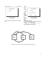
It is important to save the settings. Saving the settings means that every time the unit turns on, it
knows what it needs to do to look right. It also means that if you change something experimentally,
you can go back to where you were before. And you can always Reset to the factory default settings.

The “settings” refers to everything you setup

through the menus: Frequency, Phase, Color

Balance, Position, Flip Horz, Buzzer on or off—

everything. After you save all this, you can

change anything, then easily recall the saved

settings. The display unit always turns on with

these saved values.

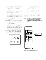
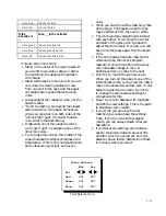
The menus for 

Save

Recall

 and 

Reset

 all

operate in basically in the same way. As the

diagram shows, there are three places where

settings are stored. 

The first storage place is the Active Settings.

This is what the unit is actually doing when it is

on. If you change anything, this is where the

change occurs. (Actually, the Active Settings

isn’t really a memory. When the power goes off,

everything in this register is lost. However, on

power up, the Saved Memory is copied into

Active Settings.)

The second storage place is Saved Memory.

When you Save, a copy of the contents of Active

Settings is placed in Saved Memory. When you

Recall settings, a copy of Saved Memory is

placed in Active Settings, and the unit follows

these instructions. Saved Memory is not lost

when the power goes off, even if the AC power

is lost.

The third storage place is Factory Default

Values. You can’t change these, of course. If you

get things all tangled, you can always Reset to

the original factory settings. This will 

not

change the Saved Memory settings. It simply

puts the factory defaults into Active Settings.

This way you can compare what you saved with

what the factory settings were without

destroying any saved values. 

To put Factory Default into Saved Memory,

Reset and then Save. 

About Reset

: The factory default values are not

the “best” values. If you Reset to the default

values, Black Level, White Level, Frequency and

Phase won’t be right, because the factory did not

have the particular computer you are using as a

source. Color Balance values won’t be right

either; they will all be 031 and 007 for white

and gray.

Summary of Contents for Leopard VN-3820-VA

Page 1: ...Leopard VN 3820 VA User Guide ...

Page 2: ......

Page 3: ...VN 3820 VA VN 3830 VA User s Guide 070 0032 06 7 October 2003 ...

Page 4: ...rosoft Corp All other names are trademarks or registered trademarks of their respective companies Disclaimer The information contained in this document is subject to change without notice Clarity Visual Systems Company makes no warranty of any kind with regard to this material While every precaution has been taken in the preparation of this manual Clarity Visual Systems shall not be liable for err...

Page 5: ... any alleged deficiency and obtains from Clarity a return authorization and b Clarity is satisfied that claimed deficiencies actually exist and were not caused by accident misuse neglect alteration improper installation repair or improper testing Clarity will have a reasonable time to make repairs to replace Products or to credit Buyer s account LIMITATIONS Any written warranty offered by clarity ...

Page 6: ... Picture Quality 3 6 3 3 1 Adjusting Black and White Levels 3 8 3 3 2 Matching Frequency Phase 3 10 3 3 3 Matching the Displays to Each Other 3 12 3 3 3 1 About Color Balancing 3 14 3 3 4 Changing the Position of the Image 3 16 3 4 Saving and Recalling the Settings 3 18 3 5 Setting Additional Controls 3 20 3 6 Controlling with RS232 Commands 3 22 Routine Maintenance Is Important 4 1 4 1 Replacing ...

Page 7: ...t 6 14 6 7 Technical Support Request 6 15 6 8 Regulatory Information 6 16 6 9 Specifications 6 17 6 10 Measurements millimeters 6 20 6 11 Measurements inches 6 23 6 12 Dimensions for Banner Installations 6 27 6 13 Making Test Patterns With Paint 6 28 Index 6 31 ...

Page 8: ...vi vi ...

Page 9: ...1 1 1 Information You Need to Know 1 1 What is the VN 3820 VA VN 3830 VA 1 2 Your Safety Is Important ...

Page 10: ...shipped with the cable tray removed for easier installation Plastic buttons are in place to cover the side to side mounting holes The batteries are already in the remote control Standard accessories One 3 m 10A IEC power cord One 3 m HD15 D sub VGA patch cable One remote control with batteries installed One upper mounting rail hanger rail One lower mounting bracket Three bolts washers and nuts for...

Page 11: ...1 3 Top cable channel Side bolt holes Lower cable channel with end cap in place Vertical cable channel Display unit front top view Two displays mounted side by side ...

Page 12: ...reen is held in place by locks secured with screws There are no user serviceable parts inside so there is no reason for a user who is not a qualified service person to open the screen The wall on which the displays will be mounted must be strong enough to hold them Each units weighs about 68 lbs 31kg Simply mounting them into wallboard won t be adequate WARNING TURN OFF POWER SWITCH BEFORE OPENING...

Page 13: ...1 5 FRONT WARNING HOT SURFAC ES NEAR LAMP SKIN BURN HAZARD Lamp housing as seen from the bottom of the display DISCONNECT POWER CORD BEFORE SERVICING NO USER SERVICEABLE PARTS INSIDE ...

Page 14: ...1 6 ...

Page 15: ...o Install the Displays 2 1 Before You Start 2 2 Two Ways to Install Display 2 2 1 How to Remove and Replace the Screen 2 2 2 Installing Hanger Method 2 2 3 Installing Flush to Ceiling 2 3 After the Units Are Hung ...

Page 16: ...ow it as stated above You can install them side by side right up against each other the units were designed specifically for this But no vertical stacking please Cable routing The units have three channels for routing cables both data and control Lower channel Beneath each unit going all the way across the bottom front is an enclosed cable channel This is open at each end so cables can run from on...

Page 17: ... filter access door Lamp access door Mirror adjustment screw rear Hole for optional lock LED panel Hanger flange Bottom rear view Viewing cone is 10 from normal Display is shown 7 feet 2 1 m high at bottom Back of display is vertical Screen normal is angled down 10 People shown are 6 feet 1 8 m tall ...

Page 18: ...r support bracket are supplied but with either method you must supply the mounting hardware The Flush Mount method can be done by attaching the display directly to the wall or by mounting the display on Unistrut or other preformed metal support system The Flush Mount method must use the lower support rail for each display This makes the units more secure To give you a general idea of the process i...

Page 19: ...n AC series 775 mm 75 mm 737 mm 19 mm Lower support rail 524 mm 68 mm 19 mm Hanger flange Upper Support Rail 13 mm hole for flush mounting Note Drawings in inches are in the Reference section on page 6 23 Rear view showing support rail dimensions and holes for flush mounting ...

Page 20: ...er row of displays it can be nearly impossible to grab the top of the screen to pull it Use the optional tool SRT 200 This accessory is two strong magnets each with about 90 lbs of pulling strength Put the magnets at corners of the wide mullion near the top Pull out sharply To remove the magnets tilt them so one of the long sides comes off 5 Rotate the screen down a little and lift it up and off T...

Page 21: ...ation of screen locking screws Screen locking screws are in the cable channel at the sides of each unit Screen locking screws in neighboring units Screen lock screws of side by side units Screen being removed ...

Page 22: ...place so the bottom of the display will rest on the lower rail when the unit is hung on the upper rail It is okay if the distance between the rails is slightly less than this it can be as little as 20 9 16 522mm but don t make it more The hanger rail is 23 584mm long They should be spaced horizontally 7 190 5mm apart The lower support rails are 30 762mm long They should be spaced 13mm apart Larger...

Page 23: ...hanger flange and upper cable channel Lower support rail 121 mm 316 mm 582 mm 609 mm 524 mm 68 mm 13 mm 13 mm Lower support rail Hanger flange Upper support rail Side view with dimensions to center of holes in support rails ...

Page 24: ...port rail provides a vital measure of safety It is a rest for some of the weight of the unit and it secures the unit to the wall Always use the lower support rail in flush mounting the displays The lower support rails are 30 762mm long They should be spaced 13mm apart Steps for mounting flush to ceiling 1 If you will use a preformed metal support system measure and mark the positions for these and...

Page 25: ... mm 19 mm Lower support rail 19 mm 592 mm 13 mm holes 2 for flush mounting Hanger flange Back view with flush mounting hole dimensions no upper support rail Note Drawings in inches are in the Reference section on page 6 23 ...

Page 26: ...s signal strength at the end of a long line Always use the best quality RS 232 cables available It saves time and headaches End caps should be installed on the two ends of the lower cable channel for a neater appearance and to keep curious hands out Open the cable channel door Clip the end cap onto the door with the slanted part toward the front of the door Secure the end cap with a screw supplied...

Page 27: ...2 13 Computer input RS 232 input and output AC power input and output 1 2 5 3 4 No more than 4 115 VAC o not connect too many units in series for AC power Four 4 display units is the limit ...

Page 28: ...2 14 ...

Page 29: ...ptimum Picture Quality 3 3 1 Adjusting Black and White Levels 3 3 2 Matching Frequency Phase 3 3 3 Matching the Displays to Each Other 3 3 3 1 About Color Balancing 3 3 4 Changing the Position of the Image 3 4 Saving and Recalling the Settings 3 5 Setting Additional Controls 3 6 Controlling With RS 232 Commands ...

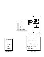
Page 30: ...NU button opens the main menu on the screen From this menu you highlight an item with the up down arrows Then press ENTER to activate the highlighted selection The PREV MENU button closes the current menu and keeps the parent menu if there is one If there isn t a parent menu this button removes the last menu ENTER selects the highlighted item and opens that menu Or if the highlighted item is like ...

Page 31: ...RESET These controls are also found in the Main Menu These two controls are not found in the Main Menu This opens the Main Menu Select or activate a feature Back up one menu level Adjust a value Move through the menu This control is not functional in this display The Remote Control ...

Page 32: ...ll power to the display Power to the neighboring units via the loop thru is not interrupted so one circuit breaker does not turn off the whole row If the circuit breaker trips off the rocker switch moves to t again he off position To reset push the switch on If it continues to trip off leave it off and contact a qualified service person Auto Lamp On The normal default state of the unit is Auto Lam...

Page 33: ...mp On if all measured temperatures are OK Flashes with LAMP ON if the lamp temperature is too high Flashes alone if the LCD is over temperature FAN On if the fan is operating properly Off if the fan is off Blinking if the fan has a locked rotor INTERLOCK On if all interlocks are closed normal operation Flashes if any interlock opens lamp door or thermal SOURCE On if a valid source is present at th...

Page 34: ...ic However the automatic sequence must be initiated manually Note Black Level and White Level must be adjusted with external black and white signals You can t use the display s internal test pattens for this Also you must use the computer that will be used for the video program If this computer changes do all these adjustments again For the Black and White external test patterns it is not necessar...

Page 35: ...rce Use the Auto for Black and for White Frequency Use a checkerboard pattern from the video source Adjust Frequency to eliminate vertical bands in the picture Phase Use a checkerboard pattern from the video source Adjust Phase for minimum horizontal noise or streaking Color Balance Use the internal white and gray patterns to match the displays to each other Section 3 3 3 Position Center the image...

Page 36: ...rols for this Here is the procedure for black and white level adjustment 1 On the remote press LEVEL This opens the Input Level menu This menu is also available from the main menu 2 With the highlight on Black Level press ENTER Black must be done before White 3 Generate a black signal from the computer source Any picture that is completely black around the upper left corner of the menu will work H...

Page 37: ...menu Always do Black Level first White Level Requires white field Auto All Level Sample Red 127 254 Green 123 255 Blue 131 255 White Level menu Black Level Requires black field Auto All Level Sample Red 127 000 Green 123 001 Blue 131 000 Black Level menu ...

Page 38: ...ess ENTER On the remote press FREQ Adjust Frequency with the right left arrow keys When the frequency is wrong you will see vertical bands of noise in the picture If there is horizontal streaking as well ignore that for now As you change frequency the number of bands will increase or decrease At one frequency there will be no bands That s what you want All displays using the same computer source e...

Page 39: ...V MENU MENU ENTER OFF COLOR FREQ CURTAIN PHASE SOURCE ON RESET Frequency and Phase Menus Remote control with location of Frequency and Phase buttons Phase Select 016 Phase Select menu Frequency Select 064 Frequency Select menu ...

Page 40: ...gh all the choices in both columns It is a common mistake to try to move between columns with the right left arrows The right left arrows change the value Highlighting the pair of arrows above either column and pressing right or left changes all three values in the column together Highlighting just the number next to Green changes the green value only 4 Adjust the Wht numbers so they are 031 for R...

Page 41: ... displays 15 Look for the display that has a gray level somewhere in between all of the other units You can use a middle brightness value this time because in gray you can adjust down and up from the 007 starting point This is the new baseline display 16 Using the Color Balance controls in the Gry column adjust all the displays to match the baseline unit starting with the units nearest to the base...

Page 42: ...ys for white and gray will make all the other colors appear the same from one display to the next However as the color of an image approaches a pure red green or blue the less control you will have when trying to match them This is why color balancing in done with whites and grays and not with primary colors It takes practice to color balance several displays quickly but patience and practice will...

Page 43: ...ays The baseline cube for gray may be different from the one for white The white and gray adjustments interact with each other If you finish the whites and start on the grays don t go back to adjust the white levels If you do you will have to do the grays again from the begin ning If the entire group has been matched for white and gray then check program material It should look fine without any ve...

Page 44: ...s hidden behind each mullion each screen border The internal Geometry test pattern helps in hiding three pixels Here is the pattern Ideally you should just see the outer edge of the 2 pixel wide magenta rectangle the 1 pixel magenta rectangle and the next two pixels of white should be completely hidden As with most ideal situations this is difficult to achieve precisely If you come within 2 pixels...

Page 45: ... air filter door indicated by arrow Up Front of Display Left right LCD adjustment screw inside air filter door indicated by white arrow A screwdriver is inserted in the adjustment screw continuously in one direction Position wraps so eventually the image will jump to the other side and continue Position ...

Page 46: ...f everything in this register is lost However on power up the Saved Memory is copied into Active Settings The second storage place is Saved Memory When you Save a copy of the contents of Active Settings is placed in Saved Memory When you Recall settings a copy of Saved Memory is placed in Active Settings and the unit follows these instructions Saved Memory is not lost when the power goes off even ...

Page 47: ... like the one on the left The cursor is in the Save brackets Whe n you push ENTER the box changes to the one on the right and the cursor is on No To save the configuration press the left arrow to highlight Yes then press ENTER The Recall Config and Reset Config menus operate in a similar way Save Config Save Save Configuration first screen Save Config Save Are you sure Yes No Save Configuration se...

Page 48: ...se to the right like reading in western cultures To change the Group and Unit numbers press ID on the remote control and highlight either number Then use the left right arrow buttons to change it The ID values are saved and recalled when you Save and Recall Settings see page 3 18 In the Misc Control menu you will find the following special controls Sharpness should always be on If the box is not c...

Page 49: ...l Sharpness 16M Colors Buzzer Enable Flip Horz Flip Vert Auto Lamp On Test Patterns Miscellaneous Controls menu Test Patterns Off White Black 50 Gray Red Green Blue Geometry Test Patterns menu Clarity Visual Systems 9025 SW Hillman Court Suite 3122 Wilsonville OR 97070 USA Tel 503 570 0700 Web www ClarityVisual com Project 573 0200 00 Version Rev A Build 0675 About menu ...

Page 50: ...ocol for communication is a 7 byte command line STX IDT CMD ETX 1 byte 2 bytes 3 bytes 1 byte Note Time from STX to ETX must be less than 1 sec STX Start of transmission character 02h IDT Monitor Identification This is used to identify which unit will execute the RS232 command The address is divided into a Group Address 1st byte and Unit Address 2nd byte There are four possible address forms Singl...

Page 51: ...d The ID number for each display is set with the remote control Press the ID button This will open a menu where you can highlight either number with the up down buttons and change it with the right left buttons RS232 command structure Start of transmission Group and Unit Identification Command End of transmission STX IDT CMD ETX 1 byte 2 bytes 3 bytes 1 byte Monitor ID Group 0 ...

Page 52: ...3 24 ...

Page 53: ...4 1 4 Routine Maintenance Is Important 4 1 Replacing Lamp and Air Filter 4 2 Cleaning the Screen and Mirror ...

Page 54: ...wn on the wire handle 5 Don t touch the face of the new lamp This lamp gets very hot and oil from you skin is not good for it Don t reach up into the lamp cavity there is nothing to fix or play with up there and you are likely to touch something that shouldn t have your skin oil on it 6 The lamp has an arrow The arrow should point toward the screen Push the new lamp into the lamp housing 7 Snap th...

Page 55: ...being removed carefully then remove it You don t need to turn off the lamp to replace the air filter 2 Remove the old filter and inspect it Replace if necessary Air filters are cheaper than lamps and LCDs The new filter goes in with the sponge side down 3 Reconnect the door close it and tighten the thumb screws ...

Page 56: ...r print for instance use a good quality optical cleaning solution and lint free paper wipes or cheesecloth The best way to clean the mirror is with clean dry compressed air This will remove most dust If the mirror has a smudge or grease spot use a cleaning solution like the ones listed here Use a new clean cloth or lint free wipe Why a new cloth Because a used cloth may have hard dirt or grit embe...

Page 57: ...4 5 Don t spray liquids directly onto the face of the screen ...

Page 58: ...4 6 ...

Page 59: ...5 1 5 If You Have Trouble 5 1 How to Fix Startup Problems 5 2 How to Fix Image Problems 5 3 Common Questions and Answers ...

Page 60: ...wer will be available on the whole line unless one of them is unplugged somewhere Is the circuit breaker on It should be lit red Is the STANDBY LED lit If it is aim the remote at the screen and press ON Is the STANDBY LED flashing or blinking If it is this is the Standby mode Wait 30 seconds for the LED to become steady then press ON Is the TEMPERATURE LED flashing If LAMP ON is also flashing the ...

Page 61: ...is too high Flashes with INTERLOCK if the thermal interlock on the lamp is tripped Flashes alone if the LCD is over temperature FAN On if the fan is operating properly Off if the fan is off Blinking if the fan has a locked rotor INTERLOCK On if all interlocks are closed normal operation Flashes if any interlock opens Flashes with TEMPERATURE if the thermal interlock is open SOURCE On if a source i...

Page 62: ...g Black and White Levels on page 3 8 Are the blacks too black Are areas in the dark parts of the image all one shade Go to Section 3 3 1 Adjusting Black and White Levels on page 3 8 Are the colors on one screen different from the colors on the other screens Go to Section 3 3 3 Matching the Displays to Each Other on page 3 12 and Section 3 4 1 Adjusting Black and White Levels on page 3 8 Are the im...

Page 63: ...5 5 ...

Page 64: ...rage lamp life is 8000 hours which means half of the lamps may fail before they reach 8000 hours The lamps are not guaranteed to have any particular length of life In the VN 3830 VA the average lamp life is 4000 hours One of the displays is darker than the others A dark display can be caused by many things check them all Start by displaying the White internal Test Pattern Long lamp use Lamps tend ...

Page 65: ... was lit since the Lamp Hours was last reset System Hours is total time electronics module had power Can I use an SVGA source No VGA 640 x 480 only What does the SOURCE button do Nothing The remote control is used with other Clarity products that have this function How do I find a qualified service person Contact the company that sold you the display Or call Clarity Visual Systems 503 570 4634 ...

Page 66: ...5 8 ...

Page 67: ...32 Commands 6 5 Installation Check List 6 6 Adjustment Check List 6 7 Technical Support Request 6 8 Regulatory Information 6 9 Specifications 6 10 Measurements millimeters 6 11 Measurements inches 6 12 Dimensions for Banner Installations 6 13 Making Test Patterns with Paint ...

Page 68: ...the Black Level and White Level menus Position Opens the Position box where the image may be moved electronically Color Balance Opens the Color Balance menu where the brightness and color of the displays are matched to each other Curtain Opens a Curtain Select box where the Curtain can be turned on and off The special Curtain button on the remote turns the Curtain on black screen and off without b...

Page 69: ...ample shows the levers in bits detected in the incoming signal 000 is black 255 is maximum white White Level Requires White field Auto Automatically adjusts the display s Black Level to the incoming video from the PC or MAC Always use this option rather than adjusting this level manually All Raises or lowers all three RGB levels together Level Sample Red 127 254 Green 126 255 Blue 131 255 Level sh...

Page 70: ...of hours lamp was on since last Lamp Hours Reset System Hours 2534 Shows number of hour system electronics module has been used Reset Lamp Hours Yes No To reset Lamp Hours use left arrow to highlight Yes then press ENTER New menu below asks for confirmation Was Lamp Changed Yes No To confirm Lamp Hours reset use left arrow to highlight Yes the press ENTER ID I The Group and Unit numbers are hexade...

Page 71: ...attern ranging from black to white left to right showing all bit levels Temperature Menu Sensor Current High Shows the current temperature at the LCD and Lamp sensors in both Celsius and Fahrenheit The High value shows the value where the TEMPERATURE LED will begin to flash LCD xxxC xxxxF xxxC Lamp xxxC xxxxF xxxC Baud Rate Menu 9 6 Kbps Chooses the baud rate for RS232 transmit and receive This ra...

Page 72: ...ll Config Recall Initiates the Recall process where previously saved values and toggle states are made current Are You Sure menu above opens Reset Config Reset Initiates the Reset process where factory default values and toggle states are made current Are You Sure menu above opens About Contains manufacturers name and contact information firmware revision letter and some manufacturing data ...

Page 73: ...th INTERLOCK if the thermal interlock on the lamp is tripped Flashes alone if the LCD is over temperature FAN On if the fan is operating properly Off if the fan is off Blinking if the fan has a locked rotor INTERLOCK On if all interlocks are closed normal operation Flashes if any interlock opens Flashes with TEMPERATURE if the thermal interlock is open SOURCE On if a source is present at the VGA c...

Page 74: ...nection 1 No connection 2 No connection 3 Receive Data RXD 4 Ground earth 5 Ground earth 6 Transmit Data TXD 7 No connection 8 No connection To change the RJ45 connectors to 9 pin D sub connectors use a standard RJ45 to 9 pin adapter and connect as follows Yellow wire pin 3 Black wire pin 2 Green wire pin 5 RJ45 9 pin 6 3 5 5 3 2 Use straight thru cables between RS232 In and Out connectors 1 Red V...

Page 75: ...gnite the lamp three times waiting 30 seconds after each try Here is the order of events from the initial application of power 1 The lighted circuit breaker is turned on 2 The electronics module goes through some initialization procedures This takes about 10 seconds 3 The fans start and the STANDBY LED flashes for another 10 seconds or so 4 The electronics module tries to ignite the lamp If it sen...

Page 76: ...isplay hours dialog box Read Lamp Hours high byte LH Read Lamp Hours low byte LL Lamp Hours Reset LRS Reset Lamp Hours to zero Read System Hours high byte TH Read System Hours low byte TL Source Controls Save All Settings SAA Recall All Settings RCA Reset All Settings RSA Input Level Offset Controls Display Input Level White Menu LVW Auto adjust White Input Level AWL Input White Level Adjust ALL L...

Page 77: ...ed 5 Green 6 Blue 7 Geometry 10 Gray Ramp Test Signal White Field WHT Test Signal Black Field BLK Test Signal 50 Gray Field GRY Test Signal Red Field RED Test Signal Green Field GRN Test Signal Blue Field BLU Test Signal Geometry Test Signal Gray Ramp GE4 Test Signal TS 0 off 1 on Test Signal Data Red TR Set test signal red level 0 255 Test Signal Data Green TG Set test signal green level 0 255 Te...

Page 78: ...ort rail is secured to internal structural members of wall Display is resting on lower support rail Display is secured to lower support rail with supplied bolts Units are side bolted Screen is installed Screen locks are up and secured with screws End caps installed for the end lower cable channel doors Power cord is connected to live AC socket No more than 4 units are in one AC loop thru series if...

Page 79: ...With a white signal from the same computer do auto adjust for White Level p 3 8 With a checkerboard signal from the computer do Frequency p 3 10 With the checkerboard pattern still there do Phase p 3 10 With an internal white test pattern on all units Color Balance for white p 3 12 With an internal gray test pattern on all units Color Balance for gray p 3 12 Position the image p 3 16 If this insta...

Page 80: ...e display if accessible Ambient air temperature Temperature at the intake air filter Describe the installation and how the displays are mounted If the display will not come on or stay on describe what the status lights on the back of the display are doing Are there any sounds coming from the display What have you done to verify the problem Clarity Visual Systems 9025 SW Hillman Court 3122 Wilsonvi...

Page 81: ... radiate radio frequency energy and if not installed and used in accordance with the instructions may cause harmful interference to radio communications However there is no guarantee that interference will not occur in a particular installation If this equipment does cause harmful interference to radio or television reception which can be determined by turning the equipment off and on the user is ...

Page 82: ...m Screen size front face Including all mullions Diagonal 37 6 955mm Width 30 2 767mm Height 22 4 569mm Mullion 0 150 4mm From edge of viewing area to edge of cube Electrical Specification Maximum Minimum Typical Notes AC requirements Line voltage 115V range 130V 90V 50 60 Hz auto ranging power factor corrected 230V range 260V 180V Line current 115V range VN 3820 2 0A 1 3A Maximum number of units i...

Page 83: ...I white 125 fL for VN 3820 150 fL for VN 3830 Using ANSI 9 point average measured normal to screen Non uniformity Using ANSI 13 point measurement Bright 25 Dim 40 Equivalent Lumens 150 Using ANSI 9 point average Viewing angle Relative to normal axis of screen Horizontal half gain 21 Vertical half gain 4 Vertical quarter gain 10 Resolution Horizontal 640 color pixels Vertical 480 color pixels Lamp ...

Page 84: ...6 18 ...

Page 85: ... Hanger flange Upper Support Rail 13 mm hole for flush mounting Rear view 6 10 Measurements millimeters Back and side views in millimeters Remember to leave an extra 25mm above the unit if you use the Hanger Method This lets you lift the unit off the upper support rail ...

Page 86: ...6 20 121 mm 316 mm 582 mm 609 mm 524 mm 68 mm 13 mm 13 mm Lower support rail Hanger flange Upper support rail Side view ...

Page 87: ...6 21 584 25 4 57 38 12 7 25 4 typ 19 Hanger rail millimeters 12 7 44 5 10 5 762 mm 25 4 38 38 19 25 4 typ 11 Lower support rail millimeters ...

Page 88: ...32 3 4 Hanger flange Upper Support Rail 1 2 hole for flush mounting Rear view inches 6 11 Measurements inches Back and side views in inches Remember to leave an extra 1 above the unit if you use the Hanger Method This lets you lift the unit off the upper support rail ...

Page 89: ...6 23 4 25 32 12 7 16 22 15 16 23 31 32 20 21 32 2 21 32 1 2 1 2 Lower support rail Hanger flange Upper support rail Side view inches ...

Page 90: ...6 24 1 2 2 1 4 3 4 1 1 typ 1 1 2 23 Hanger rail inches 1 1 2 3 4 1 1 typ 1 1 2 1 2 1 3 4 3 1 4 7 16 30 Lower support rail inches ...

Page 91: ...6 25 Bottom view showing measured locations of parts ...

Page 92: ...nput VN 3820 Current amps 2 0 4 0 6 0 8 0 10 0 12 0 Power watts 230 460 690 920 1150 1380 115 VAC Input VN 3830 Current amps 2 4 4 8 7 2 9 6 12 14 4 Power watts 276 552 828 1104 1380 1656 230 VAC Input VN 3820 Current amps 1 0 2 0 3 0 4 0 5 0 6 0 Power watts 230 460 690 920 1150 1380 230 VAC Input VN 3830 Current amps 1 2 2 4 3 6 4 8 6 0 7 2 Power watts 276 552 828 1104 1380 1656 Notes Current and...

Page 93: ... box appears Click Yes 6 Click the fill tool which looks like a paint bucket spilling paint The cursor will now be this spilling bucket when it is over the paint window the area in the middle of the screen 7 At the bottom of the screen click the Black square This is the left square on the top row of black and white boxes 8 Click somewhere in the center window It will become black 9 Click File Save...

Page 94: ...6 28 Warning box click Yes Attributes dailog box in Paint program Paint can button Color selection 9th square in bottom row Paint program location of fill bucket color selector and the 9th button ...

Page 95: ...6 29 ...

Page 96: ...4 command not executed 3 20 common questions 5 6 Computer Input 6 8 connectors 6 8 control remote 3 2 crack between 2 12 Curtain 6 4 Declaration of Conformity 6 16 depth 6 17 6 20 6 23 6 27 dimensions banner 6 27 door removing 2 6 drawings inches 6 23 millimeters 6 20 DTR RTS 3 22 end caps 1 2 2 2 2 12 Enter 3 2 ERR 3 22 fan interlock 6 9 fan LED 3 4 3 5 FCC Regulations 6 16 fL 1 2 flashing LED 3 ...

Page 97: ...cable 1 2 connectors 6 8 to 9 pin 6 8 rotate flip 3 20 RS232 cable 1 2 commands 3 22 6 5 6 10 global LED 3 5 IN 6 8 local LED 3 5 OUT 6 8 pacing 3 22 protocol 3 22 safety 1 4 6 9 Save Recall and Reset 3 18 6 6 screen angle adjustment 2 2 locks 2 6 removing 2 6 6 9 replacing 2 6 tilt 1 2 screen cleaning 4 4 select monitor 3 20 serial number 1 2 service help 5 6 manual 1 2 settings saving and recall...

Page 98: ... channel 2 12 VGA 5 7 VN 3820 VA 1 2 VN 3830 VA 1 2 wall strength 1 4 2 2 warnings 1 4 Was Lamp Changed 6 4 White Level 3 6 3 8 3 15 6 3 6 28 width 6 17 6 20 6 23 6 27 Windows Paint 6 28 wingnuts 2 12 XON XOFF 3 22 ...

Page 99: ...6 33 ...

Page 100: ...ke to comment about it please feel free to respond using this form You may fax this form to Clarity Visual Systems at 1 503 682 9441 Or you may email comments or corrections to manuals ClarityVisual com When you use email please mention the part number of the manual which starts with 070 and is on the title page What I like about this manual What I don t like about this manual Error s I found in t...

Page 101: ......
Page 102: ...ted All rights reserved Clarity Visual Systems 9025 SW Hillman Court Suite 3122 Wilsonville OR 97070 7708 USA Main Phone 1 503 570 0700 Customer Service Phone 1 503 570 4634 Fax 1 503 570 4657 www ClarityVisual com Service ClarityVisual com ...

Reviews: