background image


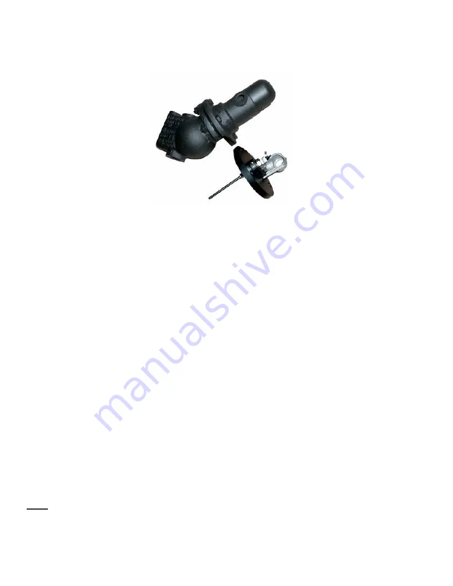
Instructions for Model EA100DRPT and EA100SRPV 

RetroPak™ Probe Cap Assemblies


Identification: 

-  Model EA100DRPT is designed to fit Model EA100 or Model EA100D Levalarms, which have 

a 4 bolt flange design. 

-  Model EA100SRPV is designed to fit Model EA100S Levalarms, which have a 6 bolt flange 

design. 
 

Installation Procedure: 

This procedure must be performed with the boiler down to prevent any false alarms or wiring 
hazard. Verify the power at the existing switch is off, before installing the upgrade. 

1.  Be certain there is no internal pressure on the Levalarm assembly. 
2.  Remove switch cover 
3.  Remove the existing wiring from switch. 
4.  Remove flange bolts (4 on EA100D models and 6 on EA100S models) and nuts. 
5.  Discard flange cover assembly with float mechanism. 
6.  Remove old flange gasket. 
7.  Install new flange gasket (Part No. C1-3). 
8.  Attach new flange cover. 
9.  Install bolts and nuts. Torque in an “X” pattern in 1/3 increments up to 70 Ft-Lbs. 
10. Mount relay control unit at convenient location. 
11. Attach high temperature wires (furnished) from probe and cap assembly (common wire) and 

           wire to relay socket terminals (See actual relay for wiring schematic diagram label). 

12. Attach original switch wires from EA100 to the new relay location on the desired switch 

           contact terminals. 

13. The relay will require a 120 VAC or 230 VAC power source depending upon the Part Number 

           (Use Relay Part No. ECID-23R for 120 VAC or Part No. ECID-56R for 230 VAC). 

14. Recheck all wiring before returning to service. 
15. Installation  is  complete. 

 
Note: The relay can be installed in user supplied enclosure with a surface mount relay socket 
(Part No. ECID-49) or the relay can be ordered already mounted in an Indoor or Outdoor 
enclosure. Refer to bulletin D3.2C and D3.3C for additional information on relay control 

options.


Summary of Contents for Levalarm EA100 Series

Page 1: ... This manual covers the following model numbers EA100D EA100S EA100SW EA100DP EA100SP EA100DRPT and EA100SRPV Section R500 532F Bulletin 532F Date 7 1 2015 Supersedes 532E 16633 Foltz Parkway Strongsville OH 44149 USA Telephone 440 572 1500 Fax 440 238 8828 www clark reliance com ...

Page 2: ...lnico V magnet The magnet attracts one leg of a U shaped armature which is attached to a micro switch leaf actuator A buoyed float holds the switch open or closed depending on which terminals are used As liquid falls in the chamber the float drops and directs the magnet to the opposite position A closed switch actuates alarms An open switch achieves fuel cut out INSTALLATION Caution Before proceed...

Page 3: ...larm After the piping has been installed to the body of the Levelarm the switch should connected by following this procedure 1 Remove the switch cover in order to access the connections on the switch assembly by loosening the screw ot the bottom of the dome shaped cover 2 Use the 7 8 Dia opening in the switch housing assembly for connecting flexible or rigid conduit when wiring the unit 3 Example ...

Page 4: ... Discard old gasket 5 Removing the flange provides complete access to the float and switch assembly 6 Inspect the float to make sure that water has not leaked directly into the float 7 Check to make sure the float and pivot rod assembly freely moves up and down and does not stick or bind 8 Inspect the magnet tube to make sure there is no contamination in the tube or attached to the magnet itself 9...

Page 5: ...uit 4 Wire per wiring diagram See below 5 Replace probe fitting housing The probe assemblies have a 5 8 24 UNEF thread and are furnished with a copper or monel gasket Stainless steel rods are connected to the probes with a coupling nut to make a complete assembly Probe installation and maintenance instructions can be found in IOM R500 E189 A 3 The probe s can be removed for inspection and cleaning...

Page 6: ...l new flange gasket Part No C1 3 8 Attach new flange cover 9 Install bolts and nuts Torque in an X pattern in 1 3 increments up to 70 Ft Lbs 10 Mount relay control unit at convenient location 11 Attach high temperature wires furnished from probe and cap assembly common wire and wire to relay socket terminals See actual relay for wiring schematic diagram label 12 Attach original switch wires from E...

Page 7: ...hrough the device The steam should not pass through for longer than 20 seconds 4 Close the steam valve 5 Close the blow down valve and simultaneously open the steam and water valves slowly bringing the equipment back to a normal operating level 6 Water should enter the Levalarm quickly when the blow down valve is closed This will indicate that the lines are free of sludge sediment or scale buildup...

Page 8: ... tube 3 Reassemble the unit Be sure to use stainless steel cotter pins if not reusing the original ones on the float rod axle pin Reinstall the Switch head assembly onto the body with a new C1 3 gasket and apply a Teflon based sealant to both sides of the gasket Lubricate the bolts with a Nickel based high temperature lubricant and torque the 4 or 6 bolts to 70 FT LB in 1 3 increments 4 Test the u...

Page 9: ...lts with a Nickel based high temperature lubricant and torque the 4 or 6 bolts to 70 FT LB in 1 3 increments 3 Test the unit for proper functioning a To test the switch assembly set the unit in a vise and make sure that the switch housing is on the same 45 degree angle as if it were mounted on the boiler piping b Attach an ohm meter to the common and normally open switch contact and manually move ...

Page 10: ...C1 3 gasket and apply a Teflon based sealant to both sides of the gasket Lubricate the bolts with a Nickel based high temperature lubricant and torque the 4 or 6 bolts to 70 FT LB in 1 3 increments SPARE PARTS PART NUMBER DESCRIPTION EA100 14X SWITCH ASSEMBLY F3S FLOAT C1 3 GASKET X172372 CAP BOLT X171501 NUT T RK T probe for models with probes up to 250 PSI V RK V probe for models with probes 251...

Reviews: