16
REPLACING THE ELECTRODE
If your arc begins to lose power (i.e., will not
cut through workpiece any longer), or the
cutting arc becomes difficult to maintain, it
may be necessary to change the electrode.
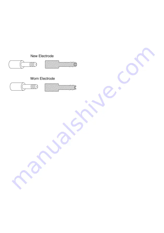
A quick visual inspection will reveal whether
an electrode is worn. A worn electrode is
characterized by a crater shaped tip. Once
this crater reaches 1.5 - 2 millimeters in
depth, replacement is necessary.
(See Figure 10)
1. Remove the nozzle cap from the torch by
turning it counterclockwise.
2. Remove the nozzle.
3. Using a wrench, unscrew the worn elec-
trode from the torch.
4. Install the new electrode by firmly tighten-
ing it in place. Only tighten electrode to
the point that it is fully seated in the
torch. Do not over-tighten.
5. Place nozzle onto electrode.
6. Replace nozzle cap by firmly turning it
clockwise onto torch assembly (refer to
Figure 9).
REPLACING THE SWIRL RING
The swirl ring has an average life expectan-
cy of about 3 - 4 cutting hours. It needs to be
replaced when cracks, chips, or burn spots
begin to appear.
1. Remove the nozzle cap from the torch by
turning it counterclockwise.
2. Remove the nozzle.
3. Slide the worn swirl ring off of the torch.
4. Install the new swirl ring by sliding it into
place on the torch.
5. Place nozzle onto electrode.
6. Replace nozzle cap by firmly turning it
clockwise onto torch assembly (refer to
Figure 9).
REPLACING THE NOZZLE CAP
The nozzle cap should be replaced if it
develops cracks or burn through holes.
Always inspect the swirl ring when replacing
the nozzle cap and replace both if necessary.
To replace the nozzle cap, simply unscrew
the old one and replace with new.
TROUBLESHOOTING
The following TROUBLESHOOTING table is
a guide to help resolve some of the more
common problems that could be encoun-
tered. Use it to help you determine a possi-
ble remedy when you are having a problem
with your plasma cutter. This table does not
provide all possible solutions, only those
possibilities considered to be common faults.
The table consists of a TROUBLE or symp-
tom, a POSSIBLE CAUSE for the symptom,
and a POSSIBLE REMEDY for that
symptom.
Figure 10.
Electrodes
Summary of Contents for 052249011064
Page 17: ...17 TROUBLESHOOTING...
Page 18: ...18 18 PLASMA CUTTER MODEL WE6493A WIRING DIAGRAM...
Page 19: ...19 19 PLASMA CUTTER MODEL WE6493A PARTS LIST...
Page 20: ...20 PLASMA CUTTER MODEL WE6493A PARTS DIAGRAM...
Page 21: ...21 PLASMA CUTTER MODEL WE6493A TORCH PARTS LIST...
Page 22: ...NOTES...
Page 23: ...NOTES...
Page 24: ...120V PLASMA CUTTER OPERATING MANUAL Model WE6493A WE6493A M001 1204...


