background image

EN

ENGLISH


Clarke

®


 American Sanders


Operator's Manual (EN) - RS-16 /RS-16DC


               FORM NO. 71121A - 7 - 


Grounded 
      Outlet

Grounding
     Pin

Grounded
Outlet
Box

(United States, Mexico and Canada)


GROUNDING INSTRUCTIONS

120 VOLT MACHINES

Instructions for connection to the power supply and 

the electrical ground.

This product must be grounded.  If it should malfunction or break-
down, grounding provides a path of least resistance for electric 
current to reduce the risk of electrical shock.  This product is 
equipped with a cord having an equipment-grounding conductor 
and grounding plug.  The plug must be inserted into an appropri-
ate oulet that is properly installed and grounded in accordance 
with all local codes and ordinances.


WARNING:  Improper connection of the equipment-

grounding conductor can result in a risk of electric shock.  
Check with a quali

fi

 ed electrician or service person if you are 

in doubt as to whether the outlet is properly grounded.  Do 
not modify the plug provided with the product - if it will not 

fi

 t 

the outlet, have a proper outlet installed by a quali

fi

 ed 

electrician. 

This product is for use on a nominal 120 volt circuit and has a 
grounding attachment plug that looks like the plug illustrated in 
Fig. 4.  Make sure that the product is connected to an outlet having 
the same con

fi

 guration as the plug.  No adaptor should be used 

with this product.


WARNING:  To prevent possible electric shock, 

protect the machine from rain.  Keep the  machine in a dry 
building.  


 WARNING:  To prevent possible electric  shock, 

always use a 3-wire electrical system connected to the elec-
trical ground.  For maximum protection against  electrical 
shock, use  a  circuit that is protected by a ground fault circuit 
interrupter.  Consult your electrical contractor.


 WARNING:  Do not cut, remove or break the ground 

pin.  If the outlet does not 

fi

 t the plug, consult your electrical 

contractor.


 WARNING:  Have worn, cut or damaged cords re-

placed by an authorized service person.

EXTENSION CORDS

Use only an approved extension cord with three conductors, a plug 
with three terminals, and a connector body with three holes.  The 
machine has a power cord with wire size 14 AWG (AWG means 
American Wire Gauge).


WARNING:  If you use an extension cord, use an 

extension cord with minimum wire size 12 AWG.  Do not use an 
extension cord longer than 50 feet.  Do not join two extension 
cords.

Figure 3

Summary of Contents for 07161A

Page 1: ...gan 48906 Fax 517 484 9836 Email CustServe Michco com Web site www Michco Com Parts Web site www FloorMachineParts Com Order Parts on Line at www FloorMachineParts Com Directly to Parts Service By Email Shop Michco com By Fax 517 702 2041 By Voice Use numbers above Serving the Cleaning Industry Since 1922 Notice All copyrighted material remains property of original owners all trademarks are proper...

Page 2: ...n Sanders machine could result in injury to you or to other personnel damage to the machine or to other property could occur as well You must have training in the operation of this machine before using it If your operator s cannot read this manual have it explained fully before attempting to operate this machine All directions given in this book are as seen from the operator s position at the rear...

Page 3: ...alifornia as identified in its Proposition 65 Regulatory Warning Law to cause cancer birth defects or other reproductive harm In certain locations including the State of California purchasers of these Products that place them in service at an employment job site or a publicly accessible space are required by regulation to make certain notices warnings or disclosures regarding the chemicals that ar...

Page 4: ...embled could result in injury or property damage Do not operate this machine until it is completely assembled Inspect the machine carefully before operation DANGER Electrocution could occur if maintenance and repairs are performed on a unit that is not disconnected from the power source Disconnect the power supply before attempting any maintenance or service Always remove the electrical plug from ...

Page 5: ...urface texture can cause a sudden pulling motion by this machine This sudden pulling motion can result in loss of control of the machine which could injure the operator or bystanders Avoid motions that could cause machine to cross from a smooth floor surface to a carpeted or rough texture floor surface Avoid motions that could allow the machine to come in contact with low obstacles such as floor e...

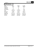
Page 6: ...ps 15 15 8 3 Pad Brush Speed 175 rpm 175 rpm 175 rpm Power 1 5 hp 1 1 kW 1 5 hp 1 1 kW 1 1 kW Gearbox 3 Planet 3 Planet 3 Planet Pad Driver Size 16 41 cm 16 41 cm 16 41 cm Cord Length 50 15 m 50 15 m 50 15 m Height w handle 46 117 cm 46 117 cm 46 117 cm Weight w cord 91 lbs 41 1 kg 91 lbs 41 1 kg 91 lbs 41 1 kg Handle Tube Tubular Steel Tubular Steel Tubular Steel Main Frame Die Cast Alum Die Cast...

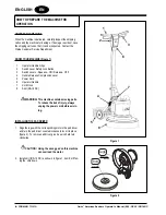
Page 7: ...Operator Handle Grips 2 Switch Lever Safety Lock Button 3 Switch Levers Squeeze ON Release OFF 4 Handle Release Compression Lever 5 Power Cord 6 Operator Handle 7 Cord Hook 8 Skirt RS 16 DC WARNING This machine contains moving parts To reduce the risk of injury always unplug the power cord before servic ing INSTALLING THE PAD DRIVER 1 Align the lugs with the corresponding slots in the pad driver a...

Page 8: ...an This product is for use on a nominal 120 volt circuit and has a grounding attachment plug that looks like the plug illustrated in Fig 4 Make sure that the product is connected to an outlet having the same configuration as the plug No adaptor should be used with this product WARNING To prevent possible electric shock protect the machine from rain Keep the machine in a dry building WARNING To pre...

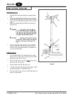
Page 9: ... go left CAUTION Immediately start moving the machine back and forth Keep the machine moving while the motor is running to avoid damage to the floor 4 Hold one of the Operator Hand Grips 1 firmly push the Safety Lock Button 2 and then compress the Switch Levers 3 to start the motor NOTE When the Switch Levers 3 are released the machine shuts off immediately AFTER USE Figure 4 1 Place the Operator ...

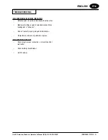
Page 10: ...pad one side is more dense than the other Machine left sitting on pad for extended period of time causing pad to take a set Pad not seated properly into pad holder bristles Warped block on brush or padholder replace MACHINE DOES NOT RUN Check plug for proper connection on machine and at wall outlet Check building circuit breaker Call for service ...

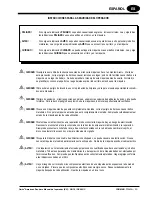
Page 11: ...as las indicaciones de dirección dadas en este libro están dadas desde la posición del operador en la parte de atrás de la máquina Puede Ud conseguir libros suplementarios dirigiéndose a su distribuidor Clarke ADVERTENCIA Los Productos a la venta en este Manual contienen o pueden contener productos químicos reconocidos por algunos gobiernos como el Estado de California según lo indica en su Propos...

Page 12: ...a reducir el peligro de explosión use la máquina sólo en locales perfectamente ventilados CUIDADO Si usa una máquina antes de que esté completamente montada corre el peligro de herirse o causar daños materiales No opere la máquina antes de que esté completamente montada Compruebe cuidadosamente el estado de la máquina antes de cada utilización CUIDADO Si efectúa un mantenimiento o una reparación s...

Page 13: ... los sitios previstos Si es preciso haga un nuevo pedido a su distribuidor Clarke AVISO Lijar madera o barnizar produce polvo que podría auto encenderse y causar lesions personales o daños mate riales Elimine de manera adecuada AVISO No use la máquina como escabel o mueble Corre el peligro de causar lesiones o daños materiales No use la máquina como medio de transporte AVISO Para evitar herirse sí...

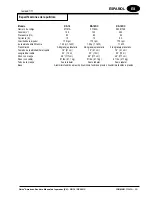
Page 14: ...1 kW 1 5 hp 1 1 kW 1 1 kW Transmisión 3 Engranaje planetario 3 Engranaje planetario 3 Engranaje planetario Tamaño de la almohadilla el cepillo 16 41 cm 16 41 cm 16 41 cm Longitud del cable 50 15 m 50 15 m 50 15 m Peso con manija 46 117 cm 46 117 cm 46 117 cm Peso con cable 91 lbs 41 1 kg 91 lbs 41 1 kg 91 lbs 41 1 kg Tubo de la manija Acero tubular Acero tubular Acero tubular Base Alumminio fundid...

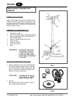
Page 15: ...tar ENCENDIDO ON Aflojar APAGADO OFF 4 Palanca de compresión para soltar la manija 5 Cable de energía 6 Manija para el operador 7 Gancho para el cable 8 Falda ADVERTENCIA Esta máquina contiene piezas en movimiento Para reducir el riesdo de lesiones siempre desconecte el cable de energía antes de realizar el mantenimiento de la máquina INSTALACIÓN DEL IMPULSOR DE ALMOHADILLA 1 Alinee las lengüetas ...

Page 16: ... caja de enchufe adecuada por un electricista autorizado Esta máquina debe funcionar en un circuito de potencia nominal de 120 V Tiene un enchufe con una clavija de puesta a tierra semejante al enchufe reproducido en la figura 3a Compruebe que la máquina esté conectada con una caja de enchufe que tiene la configuración adecuada No utilice ningún adaptador AVISO Para evitar el peligro de choque elé...

Page 17: ...mediateamente comience a mover la máquina hacia adelante y hacia atráa Para evitar dañar el piso mantenga la máquina en movimiento mientras el motor se encuentre en funcionami ento 4 Sostenga firmemente una de las manijas para el operador 1 empuje el botón de cierre de seguridad 2 y lugeo comprima las palancas de maniobras 3 para arrancar el mtoro NOTA Cuando se sueltan las palancas de maniobras 3...

Page 18: ...a almohadilla por un período de tiempo prolongado lo cual hace que la almohadilla adopten cierta forma La almohadilla no asienta adecuadamente en las cerdas del soporte de la almohadilla Bloque combado en el cepillo o en el soporte de la almohadilla cámbielo LA MÁQUINA NO FUNCIONA Verifique el enchufe para ver si está bien conectado tanto en la máquina como en la toma de pared Controle el disyunto...

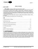
Page 19: ...cifications de la cireuse 21 Préparation de la machine avant la mise en service 22 Instructions pour le raccordement au réseau 120V 23 Fonctionnement de la machine 24 Diagnostic 25 SECTION II PIECES ET DEPANNAGE 28 32 AVERTISSEMENT LesProduitsvendusavecleprésentmanuelcontiennentoupeuventcontenirdesproduitschimiquesreconnusparcertainsgouvernements comme l État de Californie par le biais de la propo...

Page 20: ... parquet un mélange explosif de particules de fine poussière et d air peut se former Pour réduire le risque d explosion n utiliser la machine que dans des locaux parfaite ment ventilés DANGER Si vous utilisez une machine avant qu elle ne soit complètement montée vous risquez de vous blesser ou de provoquer des dégâts matériels Ne mettez pas la machine en service avant qu elle ne soit complète ment...

Page 21: ...dez en chez votre revendeur Clarke AVERTISSEMENT Le ponçage du bois ou d un vernis dégage de la poussière qui peut s enflammer et entraîner des bles sures ou des dommages Veuillex jeter en conséquence AVERTISSEMENT Ne pas utiliser cette machine comme escabeau ou comme meuble Risque de blessure ou de dégât matériel Ne pas utiliser la machine comme moyen de transport AVERTISSEMENT Pour éviter d être...

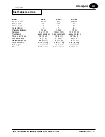
Page 22: ...sance 1 5 hp 1 1 kW 1 5 hp 1 1 kW 1 5 hp 1 1 kW Transmission 3 étages planétaires 3 étages planétaires 3 étages planétaires Tailee du patin brosse 16 41 cm 16 41 cm 16 41 cm Longueur du câble 50 15 m 50 15 m 50 15 m Hauteur avec poignée 46 117 cm 46 117 cm 46 117 cm Poids avec câble 91 lbs 41 1 kg 91 lbs 41 1 kg 91 lbs 41 1 kg Tube poignée Acier tubulaire Acier tubulaire Acier tubulaire Base Alumi...

Page 23: ...rs d interrupteur Appuyer MARCHE Relâcher ARRÊT 4 Levier de dégagement de la poignée 5 Câble d alimentation 6 Manette de commande 7 Pince pour câble 8 Jupe AVERTISSEMENT Cette machine contient des pièces mobiles Afin de réduire le risque de blessures décon nectez toujours le câble d alimentation avant de procéder à l entretien INSTALLATION DU PLATEAU 1 Alignez les tenons sur les fentes corresponda...

Page 24: ...ilisée sur un circuit d une puissance nomi nale de 120 V Elle est munie d une fiche avec broche de mise à la terre semblable à celle illustrée à la figure 3b Vérifiez que la prise à laquelle la machine doit être raccordée présente une configuration correspondant à la fiche N utilisez pas d adaptateur AVERTISSEMENT Pour éviter tout risque de choc électrique protégez la machine de la pluie Entrepose...

Page 25: ...ère Gardez la ma chine en mouvement pendant que le moteur est en fonctionnement afin d éviter que le sol ne soient endom magés 4 Tenez fermement une des prises de la poignée de l opérateur 1 poussez le bouton de verrouillage de sécurite 2 puis appuyez sur les leviers d interrupteur 3 pour faire démar rer le moteur N B Lorsque les leviers d interrupteur 3 sont relâchés la machine s éteint immédiate...

Page 26: ...stée appuyée sur la patin pendant trop longtemps causant au patin de prendre une forme incor recte Le patin n est pas placé correctement sur les poils du support du patin Bloc faussé sur le support de la brosse ou patin le remplacer LA MACHINE NE FONCTIONNE PAS Contrôlez que la prise est connectée correctement sur la machine et la prise murale Contrôlez le coupe circuit du bâtiment Contactez le se...

Page 27: ... 26 FORM NO 71121A Clarke American Sanders Operator s Manual RS 16 RS 16DC NOTES ...

Page 28: ...RS 16 RS 16 DC Section II Parts and Service Manual 71121A Clarke American Sanders Operator s Manual RS 16 RS 16DC FORM NO 71121A 27 ...

Page 29: ... 28 FORM NO 71121A Clarke American Sanders Operator s Manual RS 16 RS 16DC RS 16 RS 16 DC Assembly Drawing 1 11 ...

Page 30: ...1725A 1 Axle 19 61915A 1 Shield Inner DC 20 30725A 1 Skirt DC 21 10242A 1 Pad Driver NI 460215 1 Hard Plate Option 1 22 30381A 1 Bumper 23 80294A 4 Screw 5 16 25 61826A 1 Shield with connector DC 61715A 1 Shield STD 26 21088A 1 Main Frame 27 53650A 1 Motor 120V 53652A 1 Motor 230V 28 70499A 1 Label 29 39857A 2 Wheel 30 80292A 2 Screw 20 x 1 31 56109699 1 Cam Assy With Grip NOTE 1 35 980349 1 Washe...

Page 31: ...embly Drawing Parts List and Schematics 1 11 MOTOR PART NUMBER 40763A 40765A Part No Description Qty 40694A Capacitor Start 1 53191A Capacitor Run 1 53360A Cover Capacitor Right 2 53190A Switch Start 1 902550 Bearing Ball 6203 1 53848A Plate Mounting 1 40698A Endbell 1 41053A Cord IEC 1 747553 Strain Relief 1 ...

Page 32: ...3 4 54856A Gear Ring 1 5 54858A Cover Gearbox 1 6 56922A Retainer Bearing 1 7 58312A Shaft Planet 3 8 58313A Gear Pinion 1 9 58314A Retainer Shaft 1 10 58520A Spacer Sleeve 1 11 69195A Coupling Shaft 1 12 80141A Screw 10 32 x 1 6 13 902606 Bearing Ball 6002 3 14 902654 Bearing Ball 6204 1 15 902736 Bearing Ball 6010 1 16 902737 Bearing Needle 6 17 84808A Screw 10 24 x 3 4 6 18 53848A Plate Mountin...

Page 33: ... 32 FORM NO 71121A Clarke American Sanders Operator s Manual RS 16 RS 16DC RS 16 RS 16 DC Machine Schematic 1 06 ...

Page 34: ......

Page 35: ......

Page 36: ......

Page 37: ...A Nilfisk Advance Brand 14600 21st Avenue North Plymouth MN 55447 3408 www clarkeus com Phone 800 253 0367 Fax 800 825 2753 2010 Nilfisk Advance Inc ...

Reviews: