Page -10-
Clarke Owner's Manual -Vision 38 I\32 I/IX - 26 I/IX
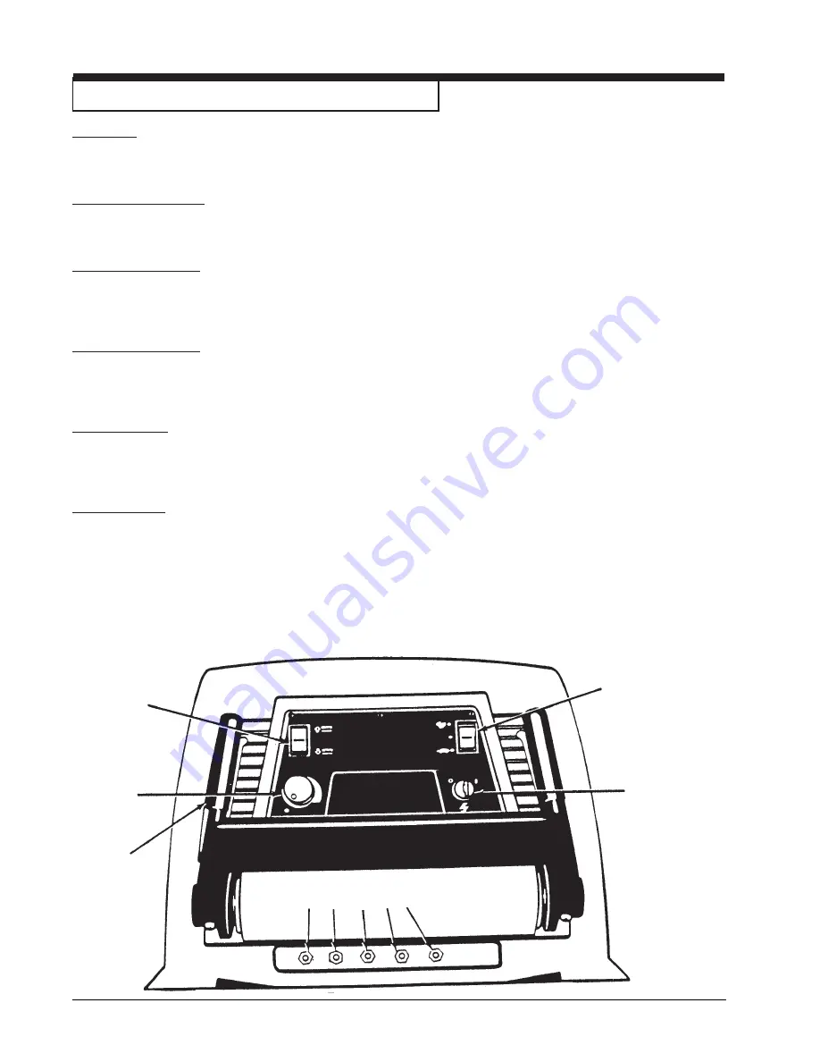
MACHINE CONTROL PANEL (38 I, 32 I & 26 I)
Key Switch
(See Figure #1, Item "A")
The key switch turns "ON" the power to the control panel. "0" is "OFF" and "1" is "on".
Traverse Speed Switch
(See Figure #1, Item "B")
The speed switch has three positions: High, Medium, and Low speeds.
Brush Position Switch
(See Figure #1, Item "C")
The brush switch has two positions: "Up" positions the brushes up; "Down" positions the brushes on the floor. The
brush motors start when the brushes are down.
Solution Control Knob
(See Figure #1, Item "D")
The solution control knob regulates the flow of cleaning solution to the floor. To increase the flow turn the knob
clockwise. To decrease the flow, turn the knob counter-clockwise.
Control Handles
(See Figure #1, Item "E")
The control handles are located at the rear of the machine. They control the direction of the machine. Push forward to
go forward. (See Figure #3, page 9). Pull back to move in reverse. (See Figure #4, page 9).
Circuit Breakers
(See Figure #1, Item "F"-"J")
The circuit breaker reset buttons are located on the rear cover, below the control handle. The breakers are located as
follows: Item F & G - Brush Motors (35A, 38I, 32I, 26I)
Item H - Traverse Motor (30A)
Item I - Vac Motor (25A)
Item J - Actuator Motor, Brush Head (5A)
If a circuit breaker trips, determine which motor is not operating and turn the key switch "OFF". Wait five minutes and
push the reset button back in. Turn the key switch "ON", and try again. An authorized service person should be
contacted if the breaker trips again.
A
B
C
D
E
F G
H
I J
Summary of Contents for 26I-00260A
Page 29: ...Clarke Owner s Manual Vision 38 I 32 I IX 26 I IX 29 NOTES...
Page 62: ...NOTES...


