background image

Clarke Owner's Manual - Vision 38 I/32 I/IX - 26 I/IX

             - 23 -

WARNING:  Maintenance and repairs must be

done by authorized personnel only.

WARNING:  Always empty the solution tank and

recovery tank before doing any
maintenance.

WARNING:  Keep all fasteners tight.

These Maintenance Procedures Must Be Done Every
Day

Keep the machine clean, it will need fewer repairs and
have longer life.

Do These Procedures When You Begin Your Work
Period

NOTE:  Always engage the parking brake before
servicing the machine.

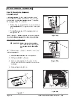
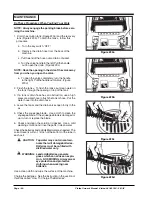
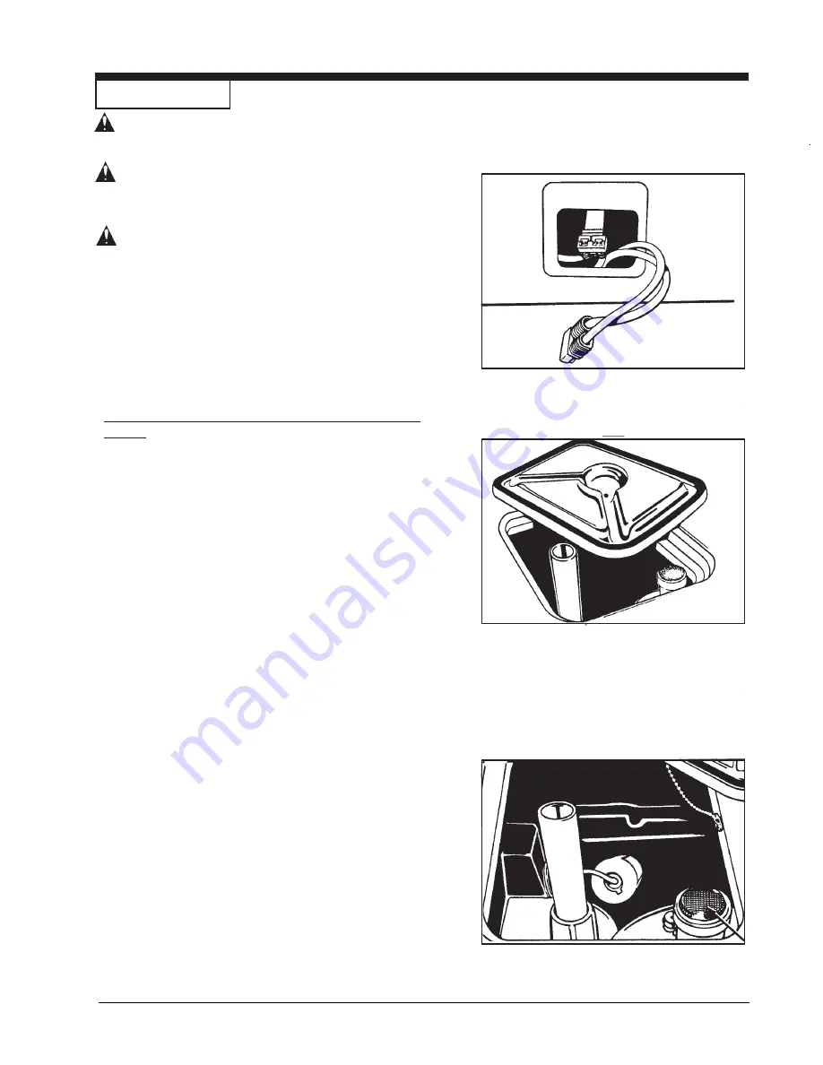
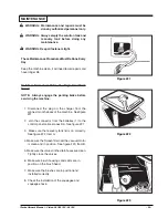
1. Disconnect the plug on the charger from the

connector on the back of the machine.  See figure
#21

2.  Join the connector from the batteries (1) to the

control panel cable connection.  See figure #21.

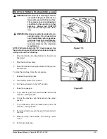
3.  Make sure the recovery tank lid is on correctly.

See figure #22, Item A.

4.  Make sure the Screen filter over the vacuum motor

is clean and in position.  See figure #23, Item B.

5.  Make sure the valves on the drain hoses are clean.

Tightly close the valves.

6.  Make sure brush housings and skirts are in
     position on the brush head.

7.  Make sure the brushes are in position and

 installed correctly

8.  Check the installation of the squeegee and

 squeegee hose.

 MAINTENANCE

Figure #21

Figure #22

Figure #23

Summary of Contents for 26I-00260A

Page 1: ...is machine before using it If you or your operator s cannot read English have this manual explained fully before attempting to operate this machine Si Ud osusoperadoresnopuedenleerelIngl s sehaganexpl...

Page 2: ...t 35 Vision 32 IX 26 IX Squeegee Squeegee Arm Assembly Drawing 36 Parts List 37 Vision 38 I 32 I 36 I Squeegee Squeegee Arm Assembly Drawing 38 Parts List 39 Vision 32 IX Brush Head Assembly Drawing 4...

Page 3: ...ore operation DANGER Machines can cause an explosion when operated near flammable materials and vapors Do not use this machine with or near fuels grain dust solvents thinners or other flammable materi...

Page 4: ...rmation are attached or fastened to the ma chine Get replacement labels and plates from your Clarke distributor WARNING Wet floor surfaces can be slippery Water solutions or cleaning materials used wi...

Page 5: ...114 liter 25 gallon 95 liter 25 gallon 95 liter Recovery Tank 30 gallon 114 liter 30 gallon 114 liter 25 gallon 95 liter ParabolicSqueegee 40 inches 37 inches 37 inches Motors Brush 2 1 hp PM 74kw 75h...

Page 6: ...kw Drive Train Direct Drive Roller Chain Direct Drive Roller Chain Brushes 2 17 inch 43cm 19 inch 48cm w 2 5cm overlap w 1 3 cm overlap Brush Speed 200 rpm 200 rpm Brush Pressure 140 lbs 165 lbs Speed...

Page 7: ...the ramp 10 Engage the parking brake 11 Turn the key switch OFF 12 Fasten the machine to the vehicle How To Remove The Machine From A Van Or Truck 1 Make sure there are no obstructions in the area 2...

Page 8: ...sion 38 I 32 I IX 26 I IX SYMBOLS USED ON VISION 38I 32I 26I Warning Also used on IX Models Power Also used on IX Models On Off Key Switch Also used on IX Models Traverse Speed Solution Control Also u...

Page 9: ...ner s Manual Vision 38 I 32 I IX 26 I IX 9 SYMBOLS USED ON VISION 32 IX 26 IX Traverse Speed Control Brush Up Down Squeegee Vacuum Brush Pressure Increase Decrease Brush Pressure Meter Battery Meter H...

Page 10: ...lockwise To decrease the flow turn the knob counter clockwise Control Handles See Figure 1 Item E The control handles are located at the rear of the machine They control the direction of the machine P...

Page 11: ...egee either 1 Up with vac motor OFF 2 Up with vac motor ON or 3 Down with vac motor ON The squeegee will automatically raise up when the control handles are pulled into reverse Control Handles See Fig...

Page 12: ...are located as follows Item K L Brush Motors 35A 32IX 26IX Item M Traverse Motor 30A Item N Vac Motor 25A Item O Actuator Motor Brush Head 5A Item P Actuator Motor Squeegee 1 5 Amp If a circuit breake...

Page 13: ...y Float Shut Off See Figure 6 The shut off switch for the vac motor is located in the recovery tank It automatically turns off the vac motor when the recovery tank is full Parking Brake See Figure 7a...

Page 14: ...Place the batteries in the tray as shown in figure 8a 8b or 8c WARNING Liftingbatterieswithout help could result in an injury Get help to lift the batteries The batteries are heavy WARNING Working wit...

Page 15: ...the cells Always top off the cells with distilled water after charging CAUTION Irreversible damage will occur to the batteries if the electrolyte level doesnotcovertheplates Keepthe electrolyte at the...

Page 16: ...on the charger To charge the batteries follow this procedure 1 Put the charger on a flat surface Make sure the ventsonthesidesareatleasttwoinchesawayfrom walls and other objects Make sure there are no...

Page 17: ...ushorpaddriverunderthebrushmotorplate See figure 14 8 Alignthelugsonthemotorgimbalwiththeslotsinthe brushgimbal 9 Pull the brush up until the gimbal locks 10 Repeat steps 7 8 and 9 to install the seco...

Page 18: ...ise the squeegee lift the squeegee lever up See figure 15b Note The center position lets the vac motor continue to run with the squeegee off the floor to avoid drips How to Fill The Solution Tank CAUT...

Page 19: ...eathathasnofurnitureandobjects until you can do the following 1 Movethemachineinastraightdirection forwardand backward 2 Stop the machine safely 3 Movethemachineinastraightdirectionafteryouturn the ma...

Page 20: ...of solution Adjust the flow of clean solution to the flowdesired 8 Move the machine across the floor in the forward direction See figure 20 1 9 Whenthemachineisonemachinelengthfromtheend of the area t...

Page 21: ...and charge the batteries Charge the batteries for a full 16 hour charge Have an authorized service person repair the charger Check voltage of each cell while discharging Connect the batteries PROBLEM...

Page 22: ...o the brush assembly casters or the solution valve The brush motors are not running The solution level is low The machine does not run The machine loses power Reset the circuit breaker Check wire conn...

Page 23: ...e 1 Disconnect the plug on the charger from the connector on the back of the machine See figure 21 2 Join the connector from the batteries 1 to the control panel cable connection See figure 21 3 Make...

Page 24: ...e a high pressure water hose to flush the tank or hose Put the water hose into the drain hose 4 Leave the tanks and the drain valves open to dry in the air 5 Check the squeegee blade Use a cloth to cl...

Page 25: ...lways engage the parking brake before serv icing the machine WARNING Alwaysweareyeprotectionandprotec tive clothing when working near bat teries NO SMOKING 1 To inspect batteries tip up recovery tank...

Page 26: ...wever they may require slight adjustment AdjustingSqueegeePressure To adjust the pressure refer to Figure 27 Proper adjustment will produce a uniform flare along the rear blade when the machine is mov...

Page 27: ...RNING Maintenance and repairs must be done by authorized personnel only WARNING Electrical repairs must be done by authorized personnel only Consult your Clarke Authorized Service Person to do the ser...

Page 28: ...A Frame Bumper one side per Kit 821203 Brush Off In Neutral Kit 14699A Solution Off In Neutral Kit 14644A PreSweep Kit 15881A NitrileSqueegeeBlades Length Machine Part No 28 12 26 30938A 38 50 26 3093...

Page 29: ...Clarke Owner s Manual Vision 38 I 32 I IX 26 I IX 29 NOTES...

Page 30: ...IX RearCoverAssemblyDrawing10 96 28 22 48 43 49 75 23 44 43 42 41 73 40 19 22 46 50 51 52 16 37 38 37 23 21 34 70 69 16 54 55 37 1 59 58 57 67 56 53 60 32 35 31 36 23 32 27 26 33 3 76 30 24 25 71 68...

Page 31: ...er 4 x x 74 55413A Key 1 x x 75 51867A Clamp Cable 1 x x 76 87029A Washer 1 x x Clarke Vision 32 IX 26 IX Rear Cover Assembly Parts List 10 96 Ref Part No Description Qty 1 49698C MainHarness 1 x x 2...

Page 32: ...83 12 42 43 44 45 22 12 84 86 84 85 4 21 47 40 1 53 51 90 77 60 61 62 56 50 54 65 67 89 88 87 72 49 68 23 31 50 59 55 63 57 18 46 75 71 74 70 48 49 1 16 15 20 14 13 23 2 8 19 4 3 82 79 7 50 11 4 3 5 6...

Page 33: ...tBreaker30A Trav 1 x x x 91 87029A Washer 1 x x x Clarke Vision 38I 32I 26I Rear Cover Assembly Parts List 7 96 Ref Part No Description Qty 1 49699D MainHarness 1 x x x 2 66533A Handle Pin 2 x x x 3 8...

Page 34: ...38 I 32 I IX 26 I IX Clarke Vision 38I 32IX 32I 26IX 26I TraverseSystemAssemblyDrawing4 96 16 17 7 15 18 19 14 13 18 11 4 10 7 24 5 9 8 7 6 5 4 3 2 1 21 22 23 41 40 39 37 38 32 37 36 35 34 33 31 16 30...

Page 35: ...x 17 60663A Brake Pedal Bracket 1 x x x x x 19 980651 Washer Flat 5 16 3 x x x x x 20 85816A Screw 5 16 18 x 1 5 Hx 1 x x x x x 21 915102 Key 1 x x x x x 22 835209 TraverseMotor 1 x x x x x 23 51828A...

Page 36: ...IX Clarke Vision 32 IX 26 IX Squeegee Squeegee Arm Assembly Drawing 10 96 34 11 ref 49 46 39 38 37 25 36 32 31 25 24 14 27 28 29 30 22 25 26 25 45 20 21 43 40 25 35 44 34 42 17 11 12 10 14 7 8 5 4 3...

Page 37: ...e Asm 1 x 18807A Squeegee Asm 29 Acc 1 x Clarke Vision 32 IX 26 IX Squeegee Squeegee Arm Assembly Parts List 10 96 Ref Part No Description Qty 20 85390A Screw 20 x 1 25 x x 21 53407A Spring Recoil 1 x...

Page 38: ...32 I IX 26 I IX Clarke Vision 38 I 32 I 26 I Squeegee Squeegee Arm Assembly Drawing 10 96 34 11 ref 45 42 33 34 35 21 37 23 22 21 20 18 19 38 39 11 12 14 10 26 15 16 46 26 11 36 1 2 3 40 4 6 5 8 7 13...

Page 39: ...x 3 4 Hex 4 x x x 19 87026A Washer Flat 5 x x x 20 920256 Nut 5 16 18Hex 2 x x x 21 81104A Nut 20 Hex ESNA x x x 22 60659A Squeegee Spring Brkt 2 x x x 23 68013A Squeegee Adj Stud 2 x x x 24 60417A A...

Page 40: ...sion 32 IX Brush Head Assembly Drawing 8 97 49 48 47 34 55 50 54 44 22 9 65 64 62 41 42 36 43 9 37 3 5 4 6 46 52 28 1 2 30 3 60 57 7 8 5 58 31 64 63 30 10 9 11 13 29 28 45 27 39 40 51 36 26 12 14 33 1...

Page 41: ...62 60659A Bracket 2 63 920110 Nut 5 16 18 ESNA 2 64 980205 Washer 3 65 85814A Screw 5 16 18 x Hex 2 66 61658A GimbalCollar 2 Clarke Vision 32 IX Brush Head Assemby Parts List 8 97 Ref Part No Descript...

Page 42: ...I 26 I IX Brush Head Assemby Parts List 8 97 47 46 45 54 53 48 52 44 67 66 65 9 51 50 7 28 57 66 64 8 5 61 31 30 7 10 9 11 12 14 62 15 16 55 56 49 17 18 20 19 21 12 11 22 40 25 63 26 13 28 29 30 27 32...

Page 43: ...Nut 5 16 18 ESNA 2 x x x x 65 60659A Bracket 2 x x x x 66 980205 Washer 3 x x x x 67 85814A Screw 5 16 18 x 1 Hx 2 x x x x Ref Part No Description Qty 1 962980 Screw 6 32 x 1 PN 4 x x x x 2 47374A Le...

Page 44: ...38 I 32I IX 26 I IX Solution Vacuum System Drawing 7 96 49 47 24 2 8 48 2 8 50 51 52 53 54 17 27 28 29 28 32 29 34 55 17 31 35 55 34 30 20 27 26 25 24 23 22 21 20 19 18 16 11 10 8 7 17 6 5 4 3 9 2 5...

Page 45: ...x x x 30 30409B SqueegeeHose 1 x x x x x Clarke Vision 38 I 32 I IX 26 I IX Solution Vacuum System Parts List 7 96 Ref Part No Description Qty 31 830208 SqueegeeAdapter 1 x x x 30123A SqueegeeAdapter...

Page 46: ...Page 46 Clarke Owner s Manual Vision 38 I 32 I IX 26 I IX Clarke Vision 38 I 32 I IX 26 I IX Brush Housing Assembly Drawing 7 96 3 4 5 2 6 7 8 9 10 11 12 13 1...

Page 47: ...x 7 69038A Strap R H 1 x x 69034A Strap R H 1 x x 69066A Strap R H 1 x 8 38224A Skirt R H 1 x x 38223A Skirt R H 1 x x 38229A Skirt R H 1 x 9 50449A Pin 1 x x x x x 10 38225A Skirt L H 1 x x 38222A Sk...

Page 48: ...ket Head 6 12 980650 Washer Lock 6 13 56922A Plate Retainer 1 14 902606 Bearing 4 15 58520A Spacer Sleeve 1 16 20304A Endshield 1 Ref Part No Description Qty 17 962794 Screw 10 24 x 1 6 18 54858A Cove...

Page 49: ...ly Leads 6 50520A CommutatorBracket 1 x x x 7 56480A Strain Relief 2 x x x 8 962546 Brush Board Screw 2 x x x 9 50517A BrushBoardAsm w springs brushes 1 x x x 10 448396 Brush Spring 4 x x x 11 40826A...

Page 50: ...7846A Ring Snap 1 2 58143A Seal Oil Small 1 3 52050A CapEnd 1 4 56668A O Ring 1 5 51176A Bearing Large 1 6 58316A Shaft Gear Gearbox 1 7 902605 Bearing Small 1 8 54883A Housing 1 9 58144A Seal Oil Lar...

Page 51: ...Fan Rotating 3 15 658201 Spacer 2 16 53908A Fan Stationary 1 17 658506 Shell 1 18 53995A Fan Air Seal 1 19 53996A Fan Stationary 1 Ref Part No Description Qty 1 51913A Clip optional 2 2 54809A Housing...

Page 52: ...ical 1 3 902547 Bearing 1 4 830402 Armature Assembly 1 5 902550 Bearing 1 6 897655 Seal Oil 1 7 830845 Bracket 1 8 962955 Screw 20 x 6 Hex 2 9 830839 Bracket Assembly 1 10 833102 Field Asm w Mag Clips...

Page 53: ...0210A 40210A 7 Fuse Assembly 912382 912382 912382 42704A 42704A 8 Strain Relief A C Cord 837525 837525 837525 747553 747553 9 Strain Relief D C Cord 747553 747553 747553 737502 737502 10 D C Cord Asse...

Page 54: ...Page 54 Clarke Owner s Manual Vision 38 I 32 I IX 26 I IX Clarke Vision 32 IX 26 IX ElectricalSchematic10 96...

Page 55: ...Clarke Owner s Manual Vision 38 I 32 I IX 26 I IX 55 Clarke Vision 38 I 32 I 26 I Electrical Schematic 10 96...

Page 56: ...Page 56 Clarke Owner s Manual Vision 38 I 32 I IX 26 I IX Clarke Vision 32 IX 26 IX ConnectionDiagram1 97 Front of Machine Tank Removed...

Page 57: ...Clarke Owner s Manual Vision 38 I 32 I IX 26 I IX 57 Clarke Vision 38 I 32 I 26 I Connection Diagram 1 97 Front of Machine Tank Removed...

Page 58: ...Page 58 Clarke Owner s Manual Vision 38 I 32 I IX 26 I IX Clarke Vision 32 IX 26 IX ConnectionDiagram1 97 Rear of Machine Rear Cover Open...

Page 59: ...Clarke Owner s Manual Vision 38 I 32 I IX 26 I IX 59 Clarke Vision 38 I 32 I 26 I Connection Diagram 1 97 Rear of Machine Rear Cover Open...

Page 60: ...Page 60 Clarke Owner s Manual Vision 38 I 32 I IX 26 I IX Clarke Vision 32 IX 26 IX ConnectionDiagram1 97 Inside Rear Cover...

Page 61: ...Clarke Owner s Manual Vision 38 I 32 I IX 26 I IX 61 Clarke Vision 38 I 32 I 26 I Connection Diagram 1 97 Inside Rear Cover...

Page 62: ...NOTES...
Reviews: