background image

12

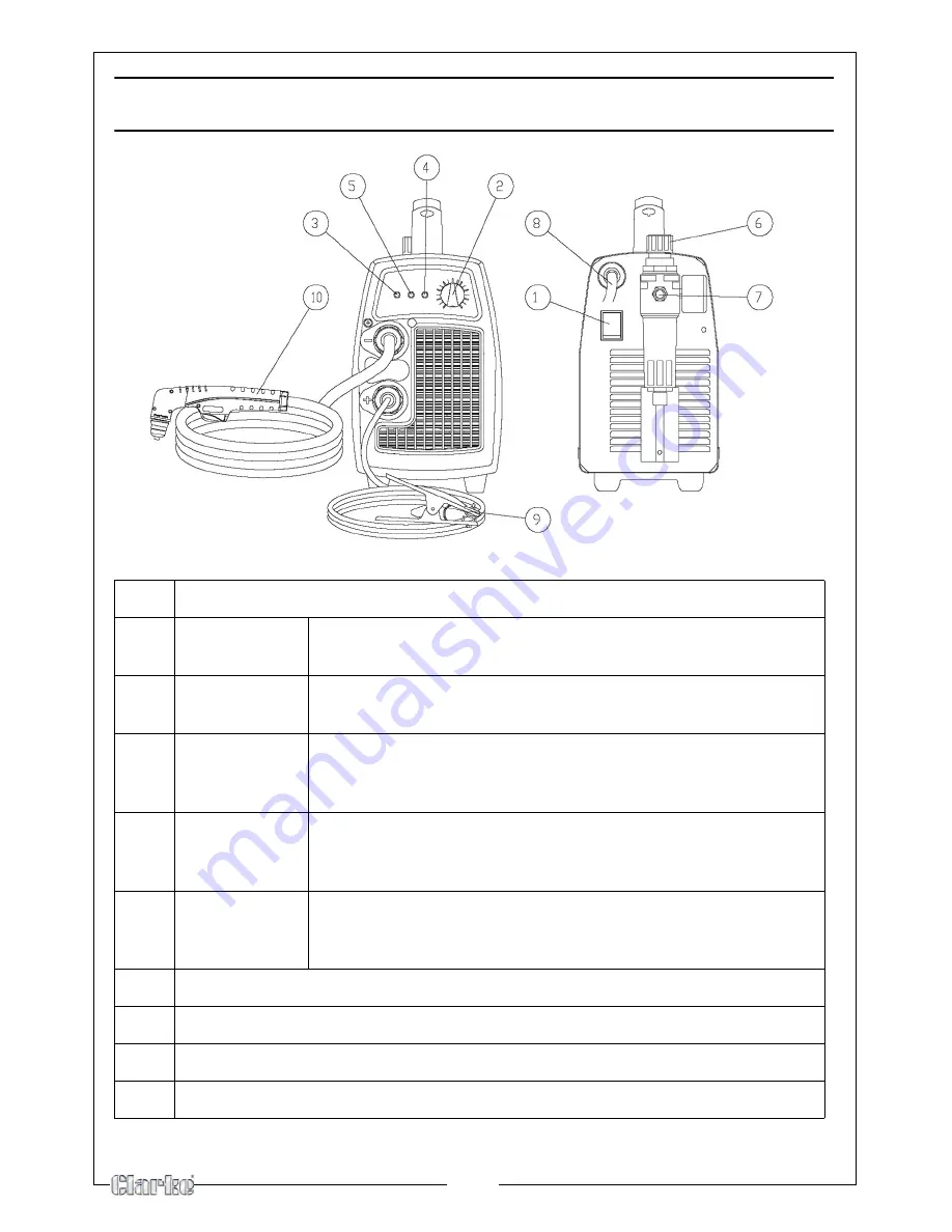
PARTS IDENTIFICATION

1

ON/OFF Switch

2

Output 
current knob

Adjusts the cutting current supplied by the machine 
according to the thickness of material/speed.

3

Green LED

Turns ON when input voltage is applied 
blinks slowly when voltage goes above 260V, or below 180V.

4

 Red LED

Turns ON when torch is triggered. Blinks quickly during 3 second 
safety pre-flow prior to pilot arc ignition. Blinks slowly if 
cutting arcs not initiated after 3 second pilot arc ignition.

5

Yellow LED

ON when the thermal protection is activated. 
Blinks slowly when the under pressure protection is working 
(the pressure is less than 3,8 Bar).

6

Air regulator

Adjusts the input air pressure - pull upward to unlock - 
nominal air pressure setting is 4,5 Bar. 
Note: the regulator should never be set above 6 Bar.

7

Compressed air connection

8

Input cord

9

Work cable with clamp

10

Torch (with a trigger security cap)

Summary of Contents for 30SI

Page 1: ...OPERATION MAINTENANCE INSTRUCTIONS LS1208 PLASMA CUTTER MODEL NO 30SI PART NO 6016010...

Page 2: ...2...

Page 3: ...our receipt which will be required as proof of purchase This guarantee is invalid if the product is found to have been abused or tampered with in any way or not used for the purpose for which it was i...

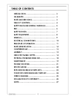
Page 4: ...MENT 8 SYMBOLS 9 ELECTRICAL CONNECTIONS 10 PRINCIPLES OF OPERATION 11 PARTS IDENTIFICATION 12 COMPRESSED AIR 13 ASSEMBLY 13 USING THE PLASMA CUTTER 14 POTENTIAL PROBLEM DURING USE 18 MAINTENANCE 19 TR...

Page 5: ...ot use in damp environments or on wet surfaces 6 Do not use the unit if the torch or cables appear damaged 7 Always turn the unit off before replacing the electrode the nozzle or the spreader tip of t...

Page 6: ...g the plasma cutting unit carry out an inspection of the surrounding area observing the following guidelines 1 Make sure that there are no other power supply cables control lines telephone leads or ot...

Page 7: ...the power transformers and the rectifying units An amber light on the front panel lights up when the thermal protection device intervenes A PNEUMATIC PROTECTION DEVICE This prevents damage to the tor...

Page 8: ...k or even better helmet large enough to cover the whole of the face equipped with safety lenses able to filter all the radiation and reduce the intensity of the light absorbed by the eye IMPORTANT saf...

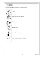
Page 9: ...9 SYMBOLS The following symbols appear on your Plasma Cutter Caution Read the Instruction Manual Mains Supply Plasma Cutting Thermal Protection Device Under Pressure Protection Device...

Page 10: ...or coloured BLACK We recommend that this machine is connected to the mains supply via a Residual Current Device RCD If in any doubt DO NOT attempt any connections or repairs yourself Consult a qualif...

Page 11: ...arc to the metal workpiece which is melted by the heat and then blown out of the way using the compressed air supply HOW THE PLASMA CUTTER WORKS The start of the cycle is determined by an arc called...

Page 12: ...nd safety pre flow prior to pilot arc ignition Blinks slowly if cutting arcs not initiated after 3 second pilot arc ignition 5 Yellow LED ON when the thermal protection is activated Blinks slowly when...

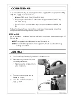
Page 13: ...result in excessive operating temperatures or damage to the plasma cutter REGULATOR An air regulator is included with the unit with an optimum pressure setting of 65 PSI 4 5 Bar NOTE The regulator sh...

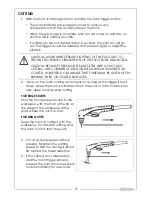
Page 14: ...ty or covered with insulating material clean the surface so that satisfactory contact between the workpiece and the earth clamp can be obtained USING THE PLASMA CUTTER The torch can be comfortably hel...

Page 15: ...old the torch perpendicular to the workpiece with the front of the tip on the edge of the workpiece at the point where the cut is to start FOR DRAG CUTS Keep the torch in contact with the workpiece Fo...

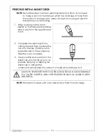
Page 16: ...d torch 2 Complete the piercing off the cutting line and then continue the cut onto the line Hold the torch perpendicular to the workpiece after the cut is complete 3 Clean spatter and scale from the...

Page 17: ...rt period of time in order to cool the torch Do not switch off the machine until the air has stopped flowing or damage may occur to the torch WARNING WHEN YOU LIFT THE TORCH AWAY FROM THE WORKPIECE TH...

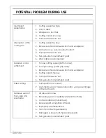
Page 18: ...low cutting speed bottom dross 2 Too high cutting speed top dross 3 Excessive distance between torch and workpiece 4 Cutting current too low 5 Torch parts are worn out 6 Non genuine manufacturer s par...

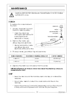
Page 19: ...same time 3 Fit a new nozzle gas diffuser ring and electrode NOZZLE DIAMETER THICKNESS OF MATERIAL BEING CUT OUTPUT CURRENT 0 80 mm 5mm 20 30 Amps 0 65 mm 5mm 10 20 Amps 4 Replace the shield cup and...

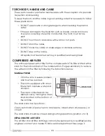
Page 20: ...ineer COMPRESSED AIR FILTER The unit is equipped with a filter for the compressed air This filter is fitted with a knob for the manual drain of the condensation Purge periodically to remove the water...

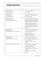
Page 21: ...r cartridge Check that air line and torch leads are free of twists and kinks GREEN LED ON YELLOW LED OFF No air flow when torch switch pressed 1 Shield cup not properly installed on torch Check that s...

Page 22: ...m Protection Class IP22 Weight 9 6 kg Dimensions L x W x H 430 x 155 x 315 mm Part No 6016010 Please note that the details and specifications contained within are correct at the time of going to print...

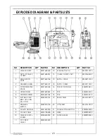
Page 23: ...10007 3 POTENTIOMETER KNOB 1 EM21690308 16 PCB FRONT PANEL 1 EM22735213 4 UPPER PANEL 1 EM21690523 17 PCB 1 EM42735123 5 DIVIDING PANEL 1 EM33620166 18 PCB 1 EM42735119 6 ELET 5313 230V BRK 1 8 3V DN...

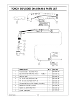
Page 24: ...LECTRODE FOR PT 25C 40 60 52582 1 EM23015187 3 AIR DIFFUSER 1 EM23015179 4 TIP D 0 8 20 30A FOR PT 40 1 EM23015186 4 TIP D 0 65 10 20A FOR PT 40 1 EM23015189 5 OUTSIDE PROTECTION NOZZLE 6 HOLES 1 EM23...

Page 25: ...25 WIRING DIAGRAM...

Page 26: ...26 DECLARATION OF CONFORMITY...

Page 27: ...27 NOTES...

Page 28: ......

Reviews: