background image

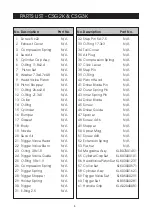
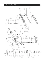
PARTS LIST - CSG2K & CSG3K

No. Description

Part No.

1

Screw 5 x22

N/A

2

Exhaust Cover

N/A

3

Compression Spring

N/A

4

Seal Air

N/A

5

Cylinder Cap Assy

N/A

6

O-Ring 11.8x2.4

N/A

7

 Piston Set

N/A

8

Washer 7.3x4.7x0.8

N/A

9

Head Valve Piston

N/A

10 Piston Stopper

N/A

11 O-Ring 26.6x2.4

N/A

12 O-Ring 21.3x3

N/A

13 Collar

N/A

14 O-Ring

N/A

15 Cylinder

N/A

16 Bumper

N/A

17 Gasket

N/A

18 Body

N/A

19 Nozzle

N/A

20 Seal. Air

N/A

21 Trigger Valve Head

N/A

22 Trigger Valve Stem

N/A

23 O-ring 3.8x1.5

N/A

24 Trigger Valve Guide

N/A

25 O-Ring 9.8x1 .9

N/A

26 Compression Spring

N/A

27 Trigger Spring

N/A

28 Trigger Stopper

N/A

29 Holder Spring

N/A

30 Trigger

N/A

31 E-Ring 2.5

N/A

 No. Description

Part No.

32 Step Pin 5x17.5

N/A

33 O-Ring 17.3x3

N/A

34 Tail Cover

N/A

35 Air Plug

N/A

36 Compression Spring

N/A

37 Click Lever

N/A

38 Step Pin

N/A

39 O-Ring

N/A

40 Piston Head

N/A

41 Driver Blade Pin

N/A

42 Outer Spring Pin

N/A

43 Inner Spring Pin

N/A

44 Driver Blade

N/A

45 Screw

N/A

46 Driver Guide

N/A

47 Spacer

N/A

48 Screw 4x16

N/A

49 Stopper

N/A

50 Upper Mag.

N/A

51 Screw 4x8

N/A

52 Extension Spring

N/A

53 Pusher

N/A

54 Magazine Assy

KLB07001451

55 Cylinder Cap Set

KLK03000101

56 Head Valve Piston Set KLK03001231

57 Collar Set

KLK03000571

58 Cylinder Assy

KLK03001621

59 Trigger Valve Set

KLK05000291

60 Trigger Set

KLB05000281

61 Handle Grip

KLA02040081

8

Summary of Contents for 3110258

Page 1: ...AIR STAPLE GUN MODELS CSG2K CSG3K Part Nos 3110260 3110258 OPERATING MAINTENANCE INSTRUCTIONS OPERATING MAINTENANCE INSTRUCTIONS...

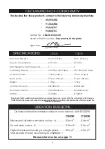
Page 2: ...of going to print However CLARKE International reserve the right to change specifications at any time without prior notice Always consult the machine s data plate DECLARATION OF CONFORMITY We declare...

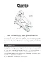
Page 3: ...it giving long and satisfactory service GUARANTEE This CLARKE product is guaranteed against faulty manufacture for a period of 12 months from the date of purchase Please keep your receipt as proof of...

Page 4: ...r yank it to disconnect from the air supply Keep hoses away from heat oil and sharp edges Check hoses for leaks or worn condition before use and ensure that all connections are secure 9 NEVER use with...

Page 5: ...not loaded then with the air supply turned OFF connect the air line to the 1 4 BSP connector A Whip Hose with Quick Fit coupling is available from your Clarke dealer 5 Both models are provided with a...

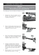
Page 6: ...essing down on the magazine catch then pull out the magazine as shown in Fig 3 3 Pull back the staple pusher against spring pressure then place the staples on the magazine ridge as shown in Fig 4 4 Ho...

Page 7: ...ours run a few drops of Clarke Air Line Oil into the air inlet before storing Notes Be aware that factors other than the tool may effect its operation and efficiency such as reduced compressor output...

Page 8: ...ger Spring N A 28 Trigger Stopper N A 29 Holder Spring N A 30 Trigger N A 31 E Ring 2 5 N A No Description Part No 32 Step Pin 5x17 5 N A 33 O Ring 17 3x3 N A 34 Tail Cover N A 35 Air Plug N A 36 Comp...

Page 9: ...PARTS DIAGRAM 9...
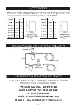
Page 10: ...16 8 SM0SF10 13 32 10 SM0SF12 15 32 12 SM0SF14 9 16 14 SM0SF16 5 8 16 CSG3K A code Inches mm SF07108 5 16 8 SF07110 3 8 10 SF07111 7 16 11 SF07113 1 2 13 SF07116 5 8 16 RECOMMENDED AIR SUPPLY CONNECTI...

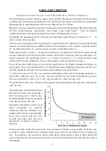
Page 11: ...lues appear in the declaration on page 7 HAND ARM VIBRATION You will note that a third value is given in the specification the highest measured reading in a single plane This is the maximum level of v...

Reviews:

Related manuals for 3110258