A - 10
CA30 20B - 56091130
7/2014
INSTRUCTIONS FOR USE
A - ENGLISH
INSTALLING BATTERIES (CONTINUED)
Install the battery with specially made battery installation tools (A, Figure 7). After the battery is installed, remove the battery installation tools,
14.
and install the battery
fi
xation bracket (B, Figure 7).
Put the battery connector (C, Figure 7) through the hole on the top of the battery box cover, put the drain hose through the right hole of
15.
the battery box cover, attach the battery box cover with 4 screws, and then install the squeegee lift cable, drain hose, and the squeegee
successively.
To charge the battery (refer to the steps stated in the maintenance section).
16.
BEFORE MACHINE START-UP
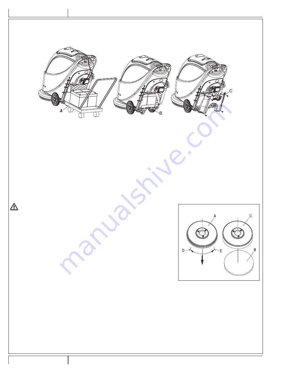
BRUSH / PAD-HOLDER INSTALLING AND REMOVAL
NOTE
According to the type of
fl
oor to be cleaned, the machine may be installed with brush (Figure 8, A), or a pad-holder (Figure 8, B and
C).
CAUTION !
When manually installing or removing the brush/pad-holder,
fi
rst ensure that all the
switches are in the “off” position and lift the squeegee off the
fl
oor. Only after which can
the brush or pad-holder be worked on. Always wear protective gloves.
Make sure the switch (41) is at the disconnecting (Off) position.
1.
Press down the handle (2) to lift the tank body (26).
2.
Put the brush (A) or the pad-holder (B – C) under the case.
3.
Use the handle (2) to lower the tank body (26) to come into contact with the brush or pad-
4.
holder.
Manually attach by following the arrow head (D) to install the brush/pad-holder (as shown in
5.
Figure 8).
Remove by turning the brush/pad-holder in the opposite direction and it can be taken off.
6.
(Figure 8)
SQUEEGEE ADJUSTING
Install the squeegee and tighten the knobs. Then connect the vacuum hose to the squeegee assembly..
7.
Adjust the squeegee through the adjusting handle (A) of the squeegee (Figure 9).
8.
If the mid-section of the rear squeegee bracket, section B, has a gap with the
fl
oor or the downward pressure is relatively light, adjust the
1)
handle in an anti-clockwise direction until the whole length of the rear squeegee strip touches well with the
fl
oor. The front squeegee strip
should lightly touch the
fl
oor.
If the two ends of the rear squeegee strip, sections C and D, have a gap with the
fl
oor or the downward pressure is relatively light, adjust
2)
the handle in a clockwise direction until the whole length of the rear squeegee strip touches well with the
fl
oor. The front squeegee strip
should Lightly touch the
fl
oor.
FIGURE 7
FRONT
FIGURE 8
Summary of Contents for 510B
Page 7: ...7 2014 A 7 56091130 CA30 20B ENGLISH A INSTRUCTIONS FOR USE 38 39 40 41 42 44 43...
Page 19: ......
Page 25: ...7 2014 B 7 56091130 CA30 20B ESPA OL B INSTRUCCIONES DE USO 38 39 40 41 42 44 43...
Page 37: ......
Page 43: ...7 2014 C 7 56091130 CA30 20B FRAN AIS C MODE D EMPLOI 38 39 40 41 42 44 43...
Page 55: ......
Page 56: ...D 2 CA30 20B 56091130 7 2014 PARTS LIST TANK SYSTEM...
Page 60: ...D 6 CA30 20B 56091130 7 2014 PARTS LIST WHEELS AND SOLUTION SYSTEM...
Page 62: ...D 8 CA30 20B 56091130 7 2014 PARTS LIST BRUSH SYSTEM...
Page 64: ...D 10 CA30 20B 56091130 7 2014 PARTS LIST SQUEEGEE SYSTEM...
Page 67: ......