background image

4

UNPACKING AND ASSEMBLY

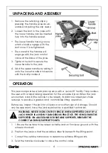
1. Remove the retaining clip by 

pressing the handle yoke down-
wards and pulling the clip away.

2. Loosen the bolt in the yoke until 

the lower handle can be inserted 
fully into the handle socket.

•  The lower handle has a groove 

which should engage with the 
bolt once it is re-tightened.

•  The socket in the handle will 

engage with the jack control 
valve at the base of the yoke.

3. Tighten the bolt to secure the 

lower handle to the jack.

4. Add the upper handle by sliding it 

onto the lower handle and secure 
with the bolt provided.

OPERATION

This jack incorporates a twin piston pump with a ‘quick lift’ facility. This provides 
the user with a rapid raising operation for the unloaded jack. When the jack 
encounters a load (the vehicle to be raised), its distance raised per stroke 
reduces to provide a gradual and controllable lifting operation.

Before use, inspect the jack for oil leaks or any other sign of damage. Should 
any be apparent, have the jack repaired by a qualified technician.

1. 1.Ensure the vehicle to be raised is stable and on firm level ground with the 

wheels chocked. 

2. Position the jack so that the saddle is directly beneath the lifting point.

•  Consult the vehicle handbook to determine suitable lifting points.

3. Twist the handle clockwise to close the control valve.

WARNING: NEVER WORK ON THE VEHICLE WHEN SUPPORTED ONLY BY A 
JACK WHICH IS A HIGHLY DANGEROUS PRACTICE. THE VEHICLE MUST BE 
SUPPORTED ON AXLE STANDS OR SUITABLE SUPPORTS, BENEATH THE 
CORRECT JACKING/SUPPORT POINTS.

Summary of Contents for 7621820

Page 1: ...OPERATION MAINTENANCE INSTRUCTIONS ORIGINAL INSTRUCTIONS GC0120 ISS 2 2 TONNE GARAGE JACK MODEL NO CTJ2QLP PART NO 7621820...

Page 2: ...2 tonne 2000kg Height of saddle from floor minimum 75 mm Height of saddle from floor maximum 510 mm Pump oil capacity 0 19L Number of strokes min max height 6 GUARANTEE This product is guaranteed agai...

Page 3: ...pported by suitable means e g axle stands NEVER rely on the jack to support the vehicle by itself 7 Never push a load off the jack 8 Ensure that all personnel are well clear of a load being raised or...

Page 4: ...th a rapid raising operation for the unloaded jack When the jack encounters a load the vehicle to be raised its distance raised per stroke reduces to provide a gradual and controllable lifting operati...

Page 5: ...vehicles jacking point rests snugly and cleanly on the axle stand and that the stand is stable before the weight is taken NOTE Ensure this operation is carried out under complete control DO NOT allow...

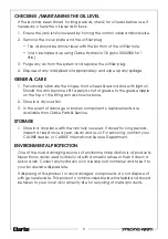
Page 6: ...grease nipple on the top of the lifting arm as shown above 2 Store in a dry location 3 In the event of damage or broken components replacements are available from Clarke Parts Service STORAGE 1 Store...

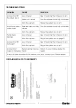
Page 7: ...osed Turn the release knob fully clockwise Air in the system Purge the system as on p 5 Pump feels Spongy Low oil level See Checking the Oil Level on p 6 Air in the system Purge the system as on page...

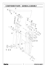
Page 8: ...8 COMPONENT PARTS GENERAL ASSEMBLY...

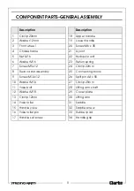
Page 9: ...spring 7 Screw M5x12 24 Circlip 22mm 8 Rear castor assembly 25 Connecting block 9 Screw M10x 12 26 Split pin A4 x 55 10 Washer M10 27 Circlip 25mm 11 Yoke bolt 28 Lifting arm shaft 12 Washer M18 29 Co...

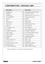
Page 10: ...0 Universal joint 10 O ring 24 6 x 5 1 31 Steel ball 6mm 11 Cylinder 32 Slow release valve seat 12 Copper sealing ring 33 Copper sealing ring 13 Body casting 34 Low pressure piston housing 14 Steel ba...

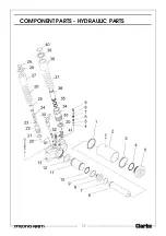
Page 11: ...11 COMPONENT PARTS HYDRAULIC PARTS...

Page 12: ......

Reviews: