background image

4

BEFORE USE

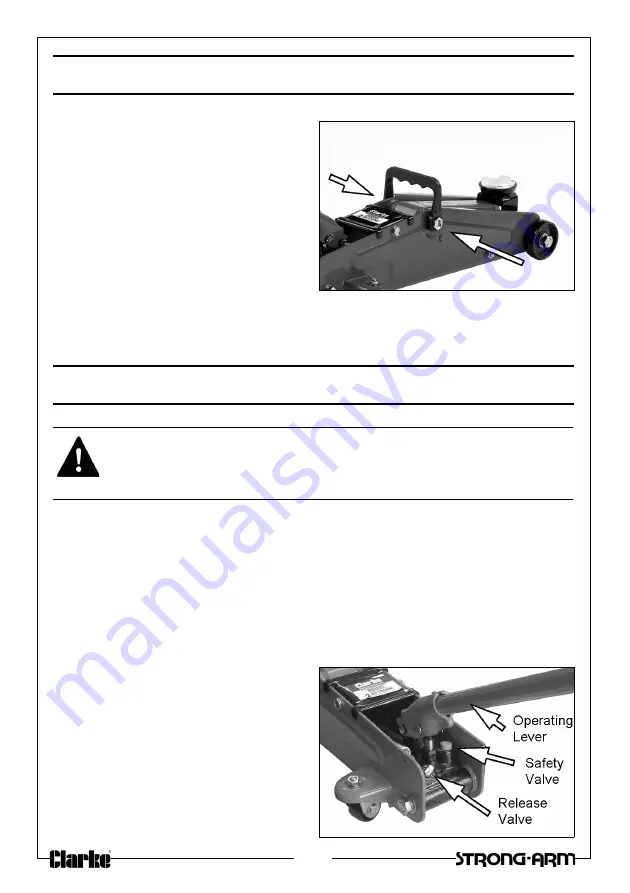
1. Before use, attach the lifting 

handle by clipping it over the two 
large nuts at the main arm pivot.

2. Inspect the jack for oil leaks or any 

other sign of damage. If in doubt, 
do not use. Should any defects be 
apparent, have the jack repaired 
by your Clarke dealer.

3. Check the piston for dirt, rust etc 

which can damage the piston 
and internal components.

The jack is now ready to use.

OPERATION

• This jack incorporates a ‘quick lift’ facility to provide the user with a 

rapid raising operation for the first five strokes of the unloaded jack. 
Thereafter, its distance raised per stroke reduces to provide a 
gradual and controllable lifting operation.

1. Ensure the vehicle to be raised is stable and on firm level ground with the 

wheels chocked.

• The jack may move slightly during operation. It is important 

therefore, that the floor is clean and completely free from debris.

2. Position the jack so that the 

saddle is directly beneath the 
lifting point.

• Consult the vehicle handbook 

to determine the lifting points.

3. Place the operating lever over the 

release valve and turn it fully 
clockwise to close the valve.

WARNING: NEVER WORK ON THE VEHICLE WHEN SUPPORTED ONLY BY A 
JACK. THIS IS HIGHLY DANGEROUS. THE VEHICLE MUST BE SUPPORTED ON 
AXLE STANDS OR SUITABLE SUPPORTS BENEATH THE CORRECT JACKING/
SUPPORT POINTS.

Summary of Contents for 7623071

Page 1: ...OPERATION MAINTENANCE INSTRUCTIONS ORIGINAL INSTRUCTIONS GC1117 ISS 1 QUICK LIFT HYDRAULIC JACK MODEL NO CTJ2250Q QM PART NO 7623071 7623073...

Page 2: ...ht of saddle from floor 135 mm Max height of saddle from floor 387 mm Weight 12 6 kg Number of full strokes to maximum height 5 stroke quick 12 in total Oil Capacity 120 ml Rated Load 2 25 tonne GUARA...

Page 3: ...9 Do not try to lift more then the rated load for the jack 10 Do not use the jack if an oil leak is apparent Consult your Clarke dealer 11 Consult the vehicle handbook to determine the correct liftin...

Page 4: ...ter its distance raised per stroke reduces to provide a gradual and controllable lifting operation 1 Ensure the vehicle to be raised is stable and on firm level ground with the wheels chocked The jack...

Page 5: ...the operating lever anti clockwise to lower the load onto the stands 8 Check constantly preferably with an assistant that the vehicle is resting correctly on the axle stands and that the stands are st...

Page 6: ...d oil appropriately and wipe up any spillage BLEEDING AIR FROM THE SYSTEM 1 Use the operating lever to turn the release valve anti clockwise relieving pressure inside the jack 2 Pump the operating lev...

Page 7: ...ase valve not fully closed Turn the release knob fully clockwise Air in the hydraulic ram Bleed air as on page 6 Pump feels spongy Low oil level Check for leakage and top up if required Air in the sys...

Page 8: ...8 COMPONENT PARTS GENERAL ASSEMBLY...

Page 9: ...h 22 Lifting Arm 6 Left Sideplate 23 Circlip 7 Circlip 24 Plastic Lifting Handle 8 Spindle 25 Cover Plate 9 Circlip 26 Hydraulic Ram Assembly 10 Lifting Saddle 27 Return Spring 11 Rotating Cup 28 Spri...

Page 10: ...10 DECLARATION OF CONFORMITY...

Page 11: ...11 USEFUL PRODUCTS IN THE CLARKE RANGE...

Page 12: ......

Reviews: