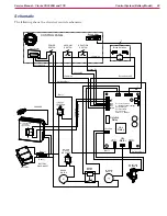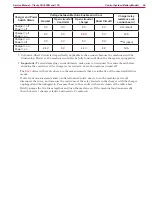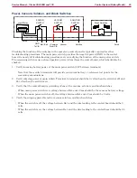
Control System (Corded Model)
17
Service Manual – Clarke CA30 20B and 17E
Removal and Installation
Rear Covers (Control Cover)
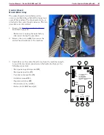
The rear covers provide access to the motor capacitors and
the system relays. Even though the upper and lower covers
are separable, it is best to treat them as a single cover during
removal and replacement.
1. Unplug the machine from power.
2. (Optional) You may wish to remove the squeegee
assembly
(E)
. When the upper cover is removed, the
squeegee will no longer be lifted by the lift cable
(F)
.
3. (Optional) If you need to separate the cover from the
machine entirely, you will need to remove the squeegee
lift cable
(F)
. Remove the bolt
(G)
and remove the cable.
4. Free the recovery drain hose from its clip and lay it to the
side.
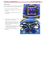
5. Remove the 6 screws (C) that secure the
upper
(A)
and lower
(B)
covers to the
machine.
•
The 2 screws
(D)
at the top of the lower
cover do not need to be removed at this
time, but may be removed later if you
wish to separate the upper and lower
covers.
6. Free the covers from the vacuum and
recovery hoses, and remove the covers.
7. To separate the cover from the machine, remove the
following wire connectors:
•
Main power
(H)
from main circuit breaker to
control panel
•
Main neutral
(I)
from power cord to control panel
•
Ground wire
(J)
from terminal lug
•
Vacuum motor circuit breaker wires
(K)
G
E
F
A
B
C
D
J
I
H
K


