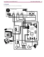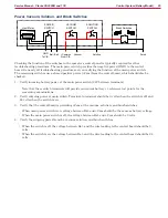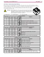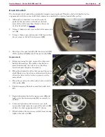
Control System (Battery Model)
33
Service Manual – Clarke CA30 20B and 17E
Battery Charger
The battery charger is located on the inside of
the rear cover, and is connected directly to the
batteries. The charger is microprocessor controlled
and uses different charging curves for optimal
performance for different battery types.
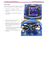
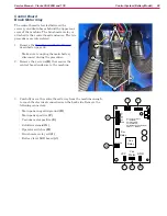
1. Remove the
Rear Covers (Control Cover)
described on page 26.
2. Disconnect the cable connector
(D)
leading to
the batteries.
3. Disconnect the two wire terminals
(E)
leading
to the control board.
4. Remove the 4 screws
(B)
that secure the
mounting straps
(C)
to the cover, and remove
the charger
(A)
.
Battery Type Dip-Switches
The charger’s functions are controlled by 4 dip-
switches (2-pair) inside the back cover. The second
2 switches should never be touched unless the
charger has been replaced and their position
needs to be confirmed. They set the battery
voltage (24V) and maximum amperage (10A), and
should always be in the Off position.
The first 2 switches are accessible through a
plastic plug without opening the charger. These
switches set the type of charge curve used for
each type of battery. The curve type signifies
the manner and magnitude in which current
and voltage are applied to the battery during its
distinct phases of the charge cycle.
1. Only if the charger is new and the 2nd pair of
DIP switches need to be confirmed, is it necessary to remove the
rear cover.
2. Remove the plastic plug covering the DIP switch access hole
(F)
.
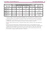
3. Set the first 2 DIP switches according to the table data below.
4. Replace the plastic plug.
Battery Type/Brand
Curve
Type
SW1
SW2
D1
D2
D1
D2
Lead-acid (Wet) batteries
IUIa-ACD
On
Off
Off
Off
Gel batteries, Exide-Sonnenschein
IUIa-GEL
Off
Off
HAZE Gel and Most AGM batteries (Default)
IUUO-GEL
Off
On
Discover AGM batteries
IUIUa-GEL
On
On
D
E
C
B
B
A
1 2
ON
1 2
ON
SW1
SW2
Off
F
F


