Service Manual-CA60 04 Control System
15
04 Control System
Functional Description
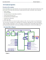
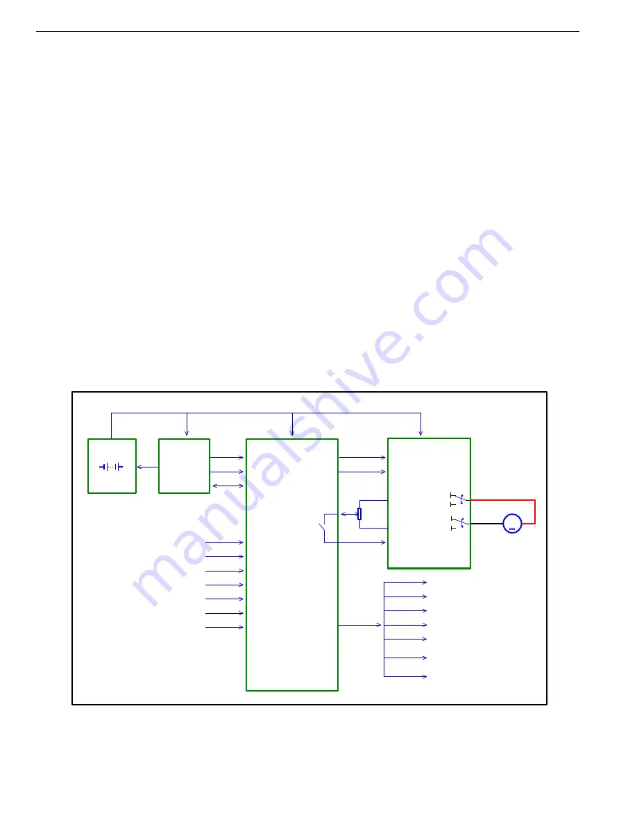
The machine utilizes a main control board (E1) to turn on various machine functions and a speed controller (E2) to control
traction speed. The E1 Main control board receives operator press button inputs, and activates various components.
Brush motor (M1)
Vacuum motor (M2)
Release brush (Only for CA60 20D and CA6020TD)
Solution flow solenoid valve (EV1)
Deck actuator (Only for CA60 20B / 24B)
Detergent pump (Option M4)
Battery type setting
The main control board (E1) also shows the battery capacity by 3 LEDs, show the running time by LED digital display
.The main control E1 can display the error message
”LO-18”,if the battery voltage falls below 18 volts, and will display
“Charg” when battery charger plug in , and so on. The system is completed by the on-board battery charger which also
uses a proprietary serial protocol to communicate with the Main Control Board (E1), In order to set the battery type.
Functional Block Diagram
1
1
2
2
3
3
4
4
5
5
6
6
7
7
8
8
D
D
C
C
B
B
A
A
CA60 Functional Block Diagram
M1
M2
E2 Curtis 1210(*1)
B+
B-
B+
B-
M
M3
Traction Motor
+
-
Speed Mode(*2)
Battery
24V
Battery Charger
CH1
Power +
Data COM
Charger In Signal
E1 Main Control Board
Brush Motor M1
Vacuum Motor M2
Detergent Pump(Option) M4
Solution Valve EV1
Brush Actuator(*3) M5
Reverse
Inhibit
Potentiometer(*1)
Pot High
Pot Low
Pot Wiper
NO
Brush Enable Button
Vacuum Enable Button
Solution EnableButton
(*5)Bush Release Button
(*6)Brush Actuator Position Selection
Brush Active Swtich
(*1) Only for CA60 20B/CA60 24B/CA60 20TD.
(*2) Only for CA60 20B/CA60 24B.
(*3) Only for CA60 20B/CA60 24B.
(*4) Only for CA60 20B/CA60 24B/CA60 20TD.
(*5) Only for CA60 20D/CA60 20TD.
(*6) Only for CA60 20B/CA60 24B.
(*4)Reverse Switch
Key Switch
(Option)Detergent Flow Control Knob
Battery Discharge Indicator(3 LEDs)
Hour Meter/Message Display
Figure 1
Summary of Contents for CA60 20B
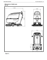
Page 15: ...Service Manual CA60 03 General Information 12 Dimensions Continues CA60 20D CA60 20TD Figure 4...
Page 16: ...Service Manual CA60 03 General Information 13 Dimensions Continues CA60 20B Figure 5...
Page 17: ...Service Manual CA60 03 General Information 14 Dimensions Continues CA60 24B Figure 6...


