


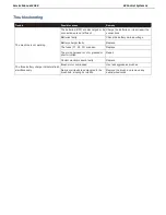


Service Manual-CA60 14 Wheel System 23
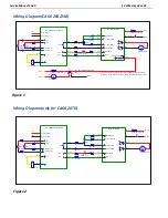
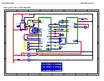
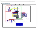
Wiring Diagram(CA60 20B/24B)
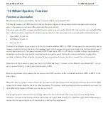
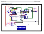
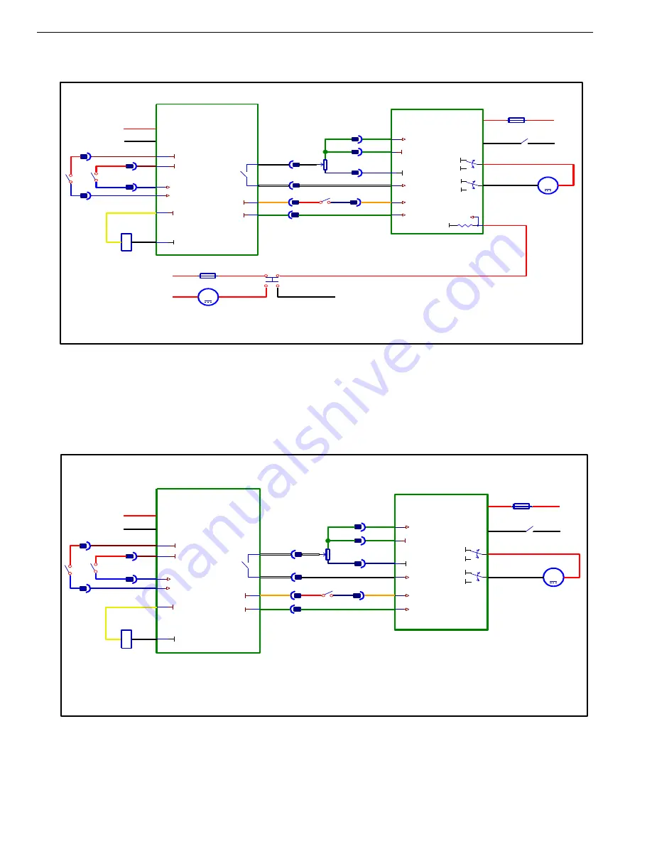
Wiring Diagram(only for CA60 20TD)
1
1
2
2
3
3
4
4
5
5
6
6
7
7
8
8
D
D
C
C
B
B
A
A
Traction System Wiring Diagram (Only For CA60 20TD)
E1 Main Control Board
Power
B-
Power Supply-
J1-18
J1-13
J1-3
J1-4
J1-17
J1-5
F3
Circuit Breaker 12A
B-
M1
M2
E2 Curtis 1210
B+
B-
B+
B-
M
M3
Traction Motor
+
-
K3
REVERSE
KSI
POT HIGH
POT LOW
POT WIPER
SPEED POT
BLK
BAT+
C5b
C5a
C5c
C5d
VR2
5K
C6
+24V
SW3
SW Reverse
C14
C12
+24V
C13
B+
B-
B+
BAT-
NO
K3
Traction Relay
+24V
J1-11
J1-8
+5V
B-
SW1
SW Brush
+24V
J1-2
J1-3
SW2
SW Brush
J1-7
J1-6
+24V
Brush Active
Brush Active
J1-5
J1-4
J1-10
J1-1
1
1
2
2
3
3
4
4
5
5
6
6
7
7
8
8
D
D
C
C
B
B
A
A
Traction System Wiring Diagram (Only For CA60 20B/24B )
E1 Main Control Board
Power
B-
Power Supply-
J1-18
J1-13
J1-3
J1-4
J1-17
J1-5
F3
Circuit Breaker 12A
B-
M1
M2
E2 Curtis 1210
B+
B-
B+
B-
M
M3
Traction Motor
+
-
K3
REVERSE
KSI
POT HIGH
POT LOW
POT WIPER
SPEED POT
BLK
BAT+
C5b
C5a
C5c
C5d
VR2
5K
C6
+24V
SW3
SW Reverse
C14
C12
+24V
C13
B+
B-
B+
BAT-
NO
K3
Traction Relay
+24V
J1-11
J1-8
K1
F1
Circuit Breaker 30A
BAT+
NC
Two Speed Mode Selection
BAT-
+5V
B-
J1-8
B-
SPEED MODE
M
M1
Brush Motor
BAT+
Speed Mode Input=24V,SPEED=82% MAX SPEED(Scrub Motor Inactive)
Speed Mode Input=OPEN,SPEED=75% MAX SPEED(Scrub Motor Active)
SW1
SW Brush
+24V
J1-2
J1-3
SW2
SW Brush
J1-7
J1-6
+24V
Brush Active
Brush Active
J1-5
J1-4
J1-10
J1-1
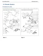
Figure 1
Figure 2
Summary of Contents for CA60 20B
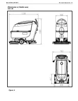
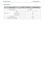
Page 15: ...Service Manual CA60 03 General Information 12 Dimensions Continues CA60 20D CA60 20TD Figure 4...
Page 16: ...Service Manual CA60 03 General Information 13 Dimensions Continues CA60 20B Figure 5...
Page 17: ...Service Manual CA60 03 General Information 14 Dimensions Continues CA60 24B Figure 6...


