Service Manual-CA60 14 Wheel System 29
Wheels Assembly with Drive System Motor disassembly/assembly (M3) (Continues)
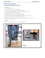
8.
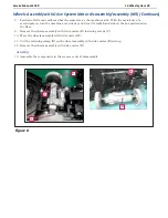
Position a flattened cardboard box the same size as the machine’s side. With the assistance of a
second person, turn the machine over sideways and rest its right-hand side on the box positioned on
the floor.
9.
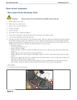
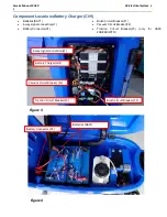
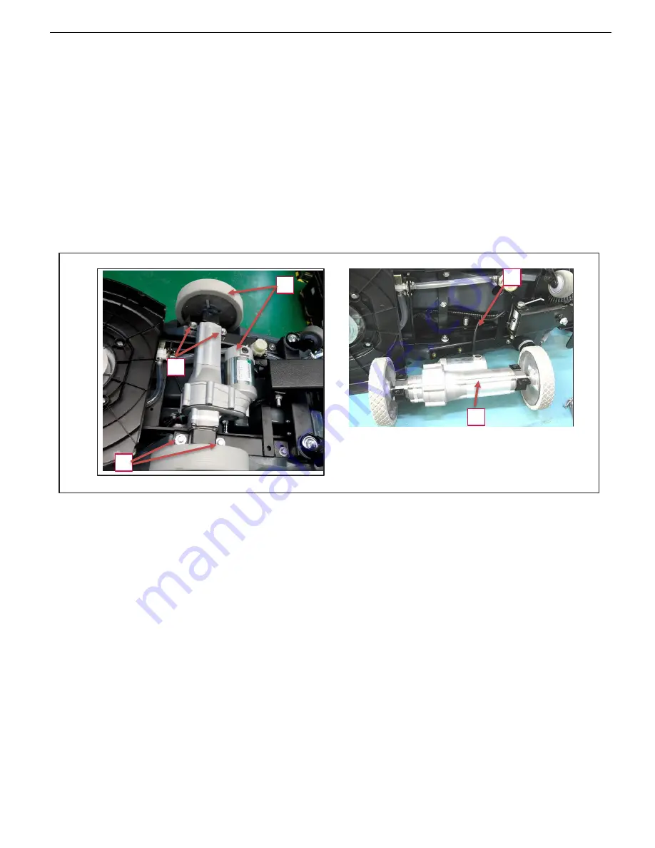
Remove the wheels assembly with drive motor (D) fastening screws (C).
10.
Move the wheels assembly with drive motor (D).
11.
Cut the retaining clamp (E) on the wheel assembly with drive motor (D) wiring.
12.
Remove the wheels assembly with drive motor (D).
Assembly
13.
Assemble the components in the reverse order of disassembly.
E
D
C
D
C
Figure 8
Summary of Contents for CA60 20B
Page 15: ...Service Manual CA60 03 General Information 12 Dimensions Continues CA60 20D CA60 20TD Figure 4...
Page 16: ...Service Manual CA60 03 General Information 13 Dimensions Continues CA60 20B Figure 5...
Page 17: ...Service Manual CA60 03 General Information 14 Dimensions Continues CA60 24B Figure 6...

