Service Manual-CA60 24-Electrical System
39
Removal and Installation
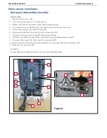
Rear panel disassembly/assembly
Disassembly
1.
Drain the recovery tank.
2.
Turn the ignition key to
“0”
and remove it.
3.
Make sure that the machine cannot move independently.
4.
Turn the recovery tank sideways, then disconnect the battery connector.
5.
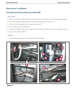
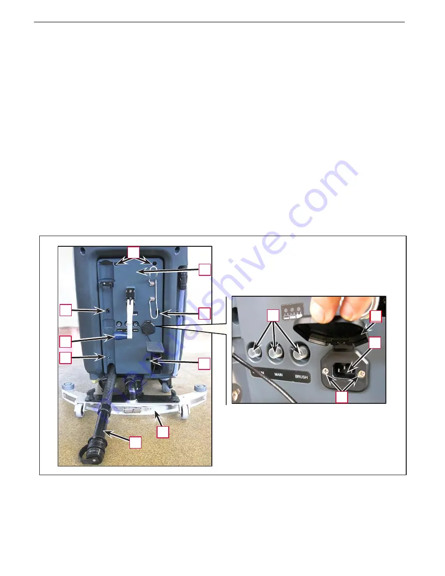
Lower the squeegee (A) with the lever (B).
6.
Disconnect and lower the recovery water drain hose (C).
7.
Unscrew and remove the caps (D) of the thermal fuses.
8.
Lift the cover (E) and unscrew the electrical connection fastening screws (F).
9.
Unscrew the screws (G), then move the rear panel (H).
10.
Disconnect the electrical connection (I) from the rear panel (H), after rotating it 90°.
11.
Remove the rear panel (H).
Assembly
12.
Assemble the components in the reverse order of disassembly.
G
H
G
G
D
E
B
I
G
G
F
A
C
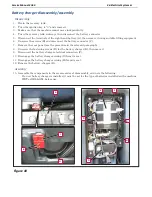
Figure 8
E
Summary of Contents for CA60 20B
Page 15: ...Service Manual CA60 03 General Information 12 Dimensions Continues CA60 20D CA60 20TD Figure 4...
Page 16: ...Service Manual CA60 03 General Information 13 Dimensions Continues CA60 20B Figure 5...
Page 17: ...Service Manual CA60 03 General Information 14 Dimensions Continues CA60 24B Figure 6...

