Service Manual-CA60 24-Electrical System
42
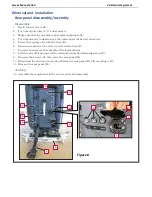
Checking/Replacing Fuses
Fuses on control panel (F1), (F3)
1.
Drain the recovery tank.
2.
Turn the ignition key to “0” and remove it.
3.
Make sure that the machine cannot move independently.
4.
Turn the recovery tank sideways, then disconnect the battery connector.
5.
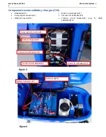
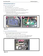
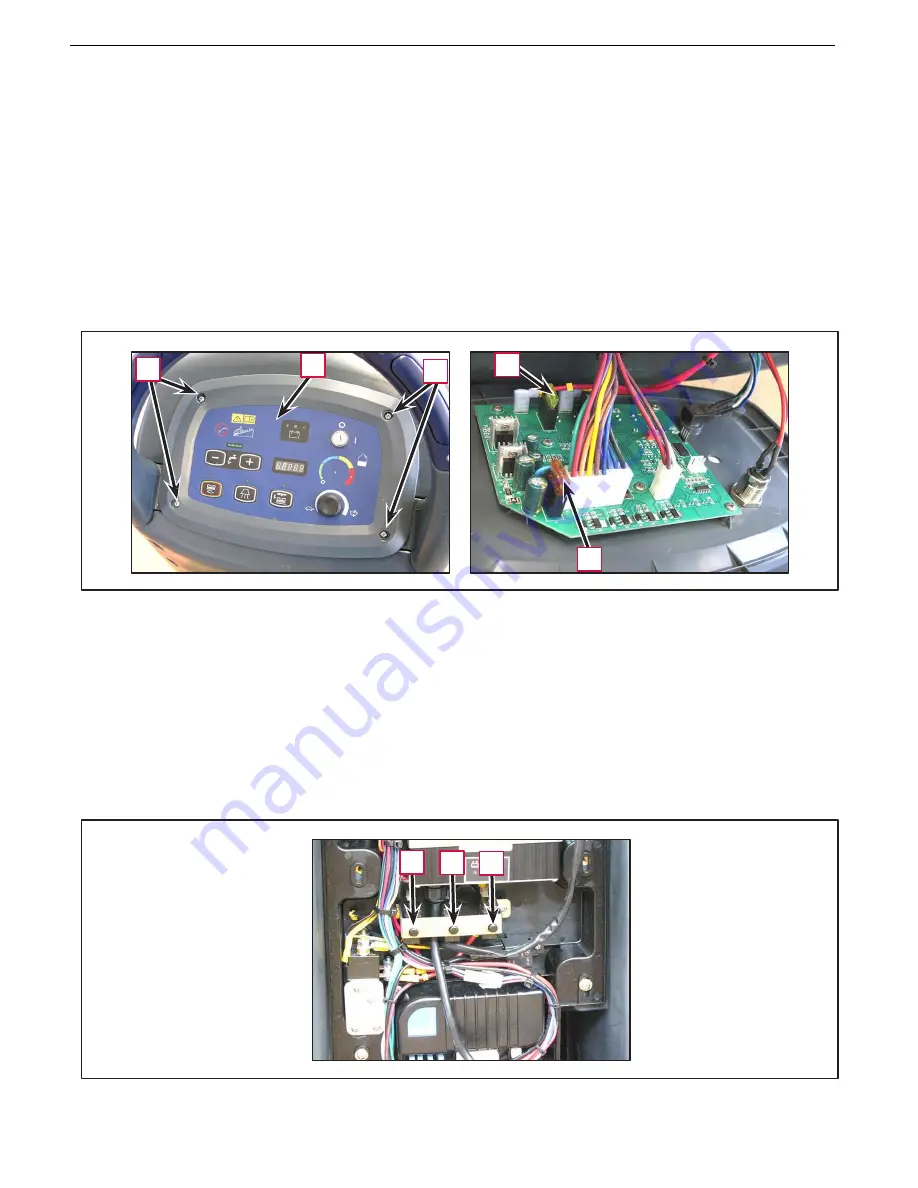
Unscrew the screws (A) and carefully move the control panel (B).
6.
Check/replace the following fuses:
•
(C): fuse (F1), rated 5 A, for protection of the control electronic board
•
(D): fuse (F3), rated 20 A, for protection of the brush motor
7.
Perform steps .4 and .5 in reverse order.
A
B
A
D
C
Fuses on control panel (F2), (F4), (F5)
1.
Remove the rear panel (see the procedure in the relevant paragraph).
2.
Remove the following thermal fuses (resettable):
•
(E): fuse (F5), rated 30 A, for protection of the vacuum motor
•
(F):
fuse (F4), rated 12 A, for protection of the drive motor (*CA60 20D/CA60 20TD)
fuse (F4), rated 17 A, for protection of the drive motor (*CA60 20B/CA60 24B)
•
(G): fuse (F2), rated 30 A, for protection of the brush rotation motor
(*): Only on machines with drive system
E
F
G
Figure 11
Figure 12
Summary of Contents for CA60 20B
Page 15: ...Service Manual CA60 03 General Information 12 Dimensions Continues CA60 20D CA60 20TD Figure 4...
Page 16: ...Service Manual CA60 03 General Information 13 Dimensions Continues CA60 20B Figure 5...
Page 17: ...Service Manual CA60 03 General Information 14 Dimensions Continues CA60 24B Figure 6...

