Service Manual-CA60 30 Solution System 48
Removal and Installation
Solenoid Valve Disassembly/Assembly (M4)
Disassembly
1.
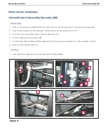
Remove the wheels assembly with drive system motor (see the procedure in the relevant paragraph).
2.
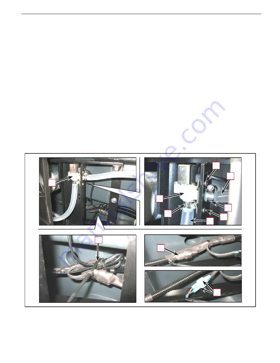
Loosen the clamps (A) and disconnect the hoses (B) from the solenoid valve (C).
3.
Unscrew the screws (D) and move the solenoid valve (C).
4.
Cut the wiring retaining clamp (E).
5.
Cut the heat-shrink tubing (F) then disconnect the electrical connections (G) on the solenoid valve (C).
6.
Remove the solenoid valve (C).
Assembly
7.
Assemble the components in the reverse order of disassembly.
D
B
C
C
A
A
D
B
E
F
G
Figure 6
Summary of Contents for CA60 20B
Page 15: ...Service Manual CA60 03 General Information 12 Dimensions Continues CA60 20D CA60 20TD Figure 4...
Page 16: ...Service Manual CA60 03 General Information 13 Dimensions Continues CA60 20B Figure 5...
Page 17: ...Service Manual CA60 03 General Information 14 Dimensions Continues CA60 24B Figure 6...

