


Service Manual-CA60 34 Scrub System DISC(CA60 20D/20TD) 56
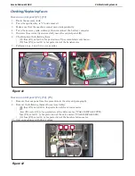
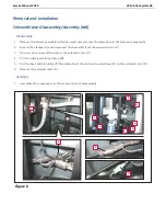
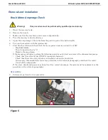
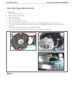
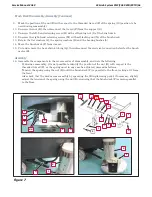
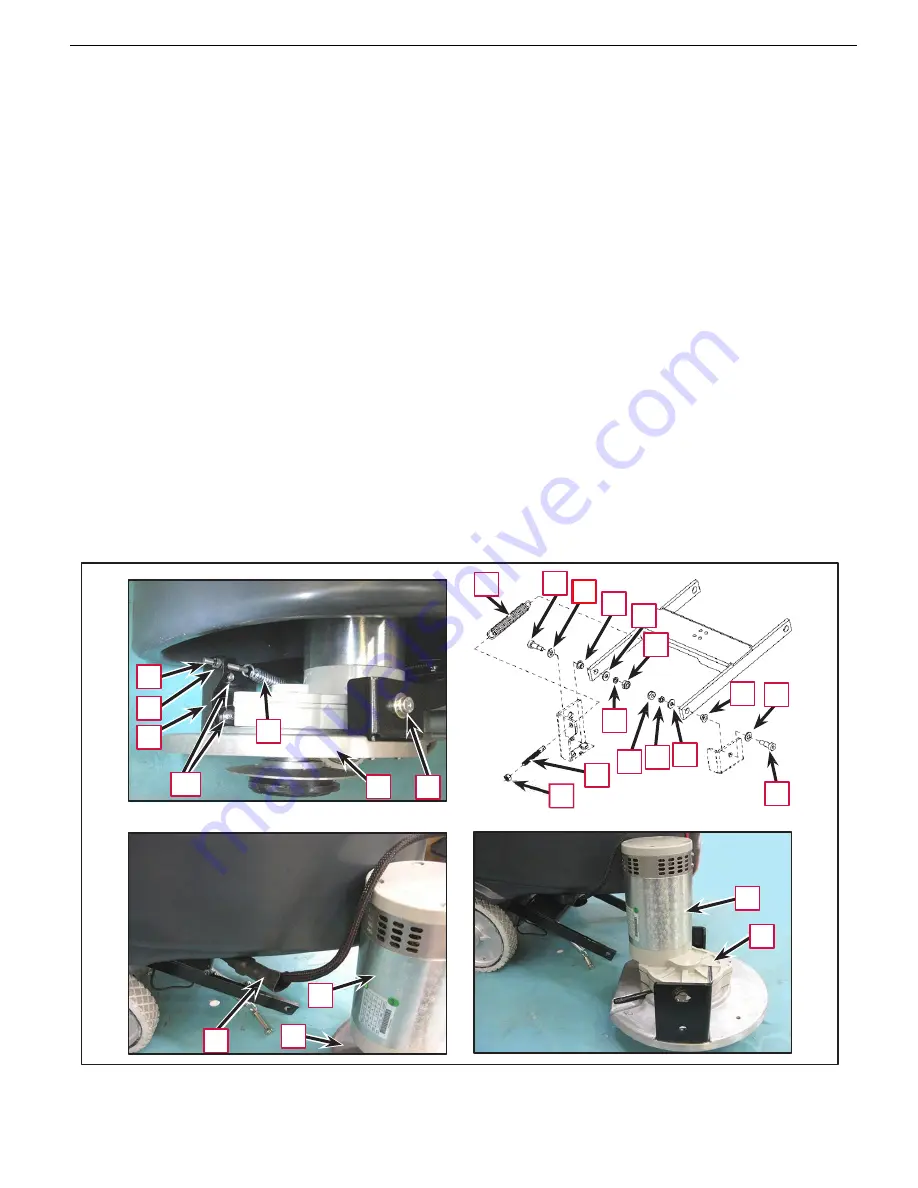
Brush Deck Disassembly/Assembly (Continues)
9.
Mark the position of the nut (E) with respect to the threaded tie rod (F) of the spring (G) (position to be
used during reassembly).
10.
Unscrew the nut (E), then disconnect the tie rod (F) from the support (S).
11.
Unscrew the left-hand retaining screw (H) with self-locking nut (I) of the brush deck.
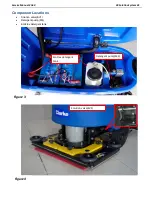
12.
Unscrew the right-hand retaining screws (M) with self-locking nut (N) of the brush deck.
13.
Retain the flat washers (J), the spring washers (K) and the bearing bushes (L).
14.
Move the brush deck (P) from its seat.
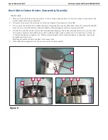
15.
Cut and remove the heat-shrink tubing (Q), then disconnect the electrical connection below for the brush
motor (R).
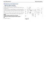
Assembly
16.
Assemble the components in the reverse order of disassembly, and note the following.
•
If, during reassembly, it is not possible to identify the position of the nut (E) with respect to the
threaded tie rod (F), or the spring must in any case be adjusted, proceed as follows:
•
Tension the spring using the nut (E) until the brush deck (P) is parallel to the floor, looking at it from
the front.
•
Also check that the deck moves smoothly by operating the lifting/lowering pedal; if necessary, slightly
adjust the tension of the spring using the nut (E), ensuring that the brush deck (P) remains parallel
to the floor.
G
M
J
L
J
N
F
E
S
G
M-N
P
H
L
J
K
I
K
J
F
E
H
R
P
R
Q
P
Figure 7
J
Summary of Contents for CA60 20B
Page 15: ...Service Manual CA60 03 General Information 12 Dimensions Continues CA60 20D CA60 20TD Figure 4...
Page 16: ...Service Manual CA60 03 General Information 13 Dimensions Continues CA60 20B Figure 5...
Page 17: ...Service Manual CA60 03 General Information 14 Dimensions Continues CA60 24B Figure 6...