Service Manual-CA60 40 Recovery System 84
Maintenance and Adjustment
1.
Drive the machine on a level floor.
2. Ensure that the machine is off and the ignition key has been removed.
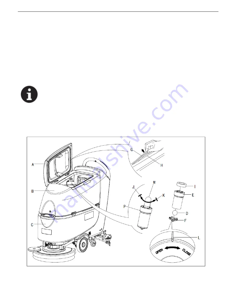
3. Turn the recovery tank lid (A, Figure 4) 90 degree position where it can be took off from the tank, and then take
down the float ball filter (P) from the tank.
4. Clean the recovery tank lid (A), recovery tank (B), clean water tank(C) and the float ball filter support frame (E).
Empty the recovery tank with the drain hose.
5.If necessary, follow the symbols
“
OPEN
”
and
“
CLOSE
”
as shown in (Figure 4) to open the bottom cover (F) of
float ball filter and then clean the float ball (D), filter support frame (E) and filter sponge (I). After cleaning, fix
the float ball (D) into the filter support frame (E) and then align the mark groove (L) of the bottom cap (F) of the
float ball filter with the mark groove (L) of the float filter support frame (E). Screw the bottom cap of the float
ball filter tight, and fix the filter sponge (I) onto the float filter support frame (E). Finally, connect it to the
sewage suction hose (M).
6. Inspect the integrity of the tank sealing strip.
NOTE
Tank sealing strip (G) makes to produce the vacuum inside the tank when suction motor works. The
tank must be sealed can effectively absorb the water from the ground to recovery tank.
7.
Check whether the contact surface of sealing strip (G) is integrity and sealing is sufficient. If necessary, take the
sealing strip of the tank out of the groove (H) and replace it. Assembly the new sealing strip as shown in
(Figure 4), the joint should be back in the middle area.
8.Close the recovery tank lid (A).
Figure 4
Summary of Contents for CA60 20B
Page 15: ...Service Manual CA60 03 General Information 12 Dimensions Continues CA60 20D CA60 20TD Figure 4...
Page 16: ...Service Manual CA60 03 General Information 13 Dimensions Continues CA60 20B Figure 5...
Page 17: ...Service Manual CA60 03 General Information 14 Dimensions Continues CA60 24B Figure 6...


