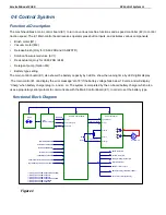
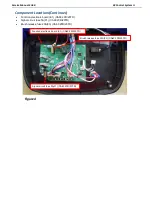
Service Manual-CA60 04 Control System
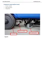
20
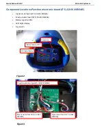
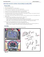
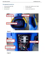
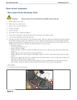
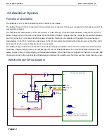
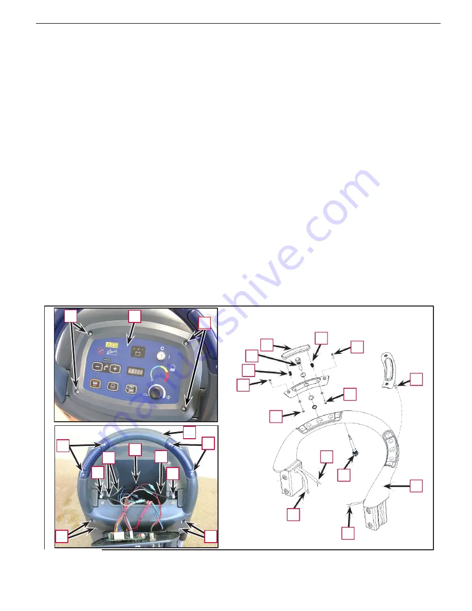
Handlebar and drive switches disassembly/assembly (ES3)
Disassembly
1.
Drain the recovery tank.
2.
Turn the ignition key to
“0”
and remove it.
3.
Make sure that the machine cannot move independently.
4.
Turn the recovery tank sideways, then disconnect the battery connector.
5.
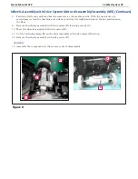
Unscrew the screws (A) and carefully move the control panel (B).
6.
Unscrew the screws and detach the retaining clamps (C) from the wiring.
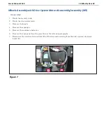
7.
In zone (D), disconnect the electrical connections for the wiring (E), ensuring you note down the colors of
the individual wires for reference during reassembly.
8.
Loosen the screws inside the holes (F) (with a 6 mm hex socket wrench), then remove the handlebar (G)
from its seat.
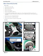
9.
If necessary, proceed as follows to remove the drive switches (H).
•
Unscrew the screws (I) and detach the switch assembly.
•
Unscrew the inner screws (J) and remove the plate (K) and the springs (L).
•
Apply a feeler to the end (M) of the cable of the switch (H) concerned, then remove the switch with
cable and leave the feeler in its place (to be used to reinsert the cable during reassembly).
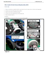
10.
If necessary, proceed as follows to remove the reverse switch (N).
•
Remove the switch (N) from its seat using a small blade screwdriver.
•
Apply a feeler to the end (P) of the cable of the switch (N), then remove the switch with cable and
leave the feeler in its place (to be used to reinsert the cable during reassembly).
Assembly
11.
Assemble the components in the reverse order of disassembly.
A
B
L
K
I
H
L
H
I
J
J
G
I
I
D
E
E
P
C
C
N
G
M
F
F
M
Figure 6
A
Summary of Contents for CA60 20B
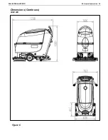
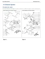
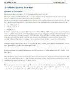
Page 15: ...Service Manual CA60 03 General Information 12 Dimensions Continues CA60 20D CA60 20TD Figure 4...
Page 16: ...Service Manual CA60 03 General Information 13 Dimensions Continues CA60 20B Figure 5...
Page 17: ...Service Manual CA60 03 General Information 14 Dimensions Continues CA60 24B Figure 6...