
Service Manual-CA60 14 Wheel System 27
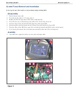
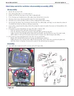
Removal and Installation
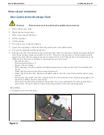
Drive System Motor Amperage Check
Warning!
This procedure must be performed by qualified personnel only.
1.
Drain the recovery tank.
2.
Drain the clean water tank.
3.
Drive onto a smooth, flat floor.
4.
Lift the squeegee.
5.
Lift the brush.
6.
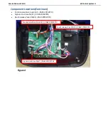
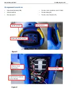
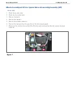
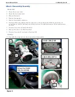
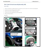
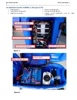
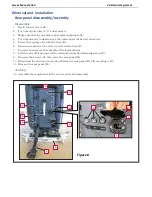
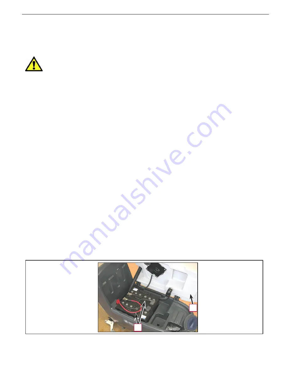
Turn the recovery tank (A) sideways.
7.
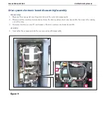
Apply the amp clamp on the cable from the positive pole of the batteries (B).
8.
Turn on the machine with the ignition key.
9.
Taking great care and ensuring safety conditions allow, drive the machine at minimum speed and check
that the motor power draw is around 2.5 A at 24 V. Then drive the machine at the maximum possible
speed and check that the motor power draw is around 15 A at 24 V. Repeat the test driving at least two
different directions across the floor to compensate for any unevenness.
•
Stop the machine.
•
Turn the ignition key to “0”.
•
Remove the amp clamp.
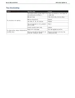
If the amperage is higher, perform the following procedures to detect and correct the abnormal am-
perage:
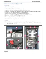
•
Check that the relevant fuse (F4) is properly fastened.
•
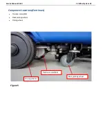
Check that there is no dirt, debris or entangled cords on the drive wheel hubs and the rear steering
wheels.
•
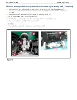
If necessary, disassemble the drive system motor (see the procedure in the relevant paragraph), and
check the condition of all its components.
If the above-mentioned procedures do not produce the correct readings for the drive system motor
power draw, the motor must be replaced (see the procedure in the relevant paragraph).
Reassembly
10.
Perform step 6 in reverse order.
A
B
Figure 6
Summary of Contents for CA60 20B
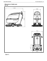
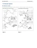
Page 15: ...Service Manual CA60 03 General Information 12 Dimensions Continues CA60 20D CA60 20TD Figure 4...
Page 16: ...Service Manual CA60 03 General Information 13 Dimensions Continues CA60 20B Figure 5...
Page 17: ...Service Manual CA60 03 General Information 14 Dimensions Continues CA60 24B Figure 6...