


Service Manual-CA60 24-Electrical System
33
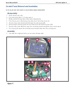
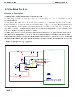
24 Electrical System
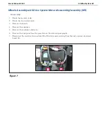
Functional Description
The batteries (2 x 12V) are connected together in series by the cables.
The battery charger (CH1) is connected to the machine by two connectors (C1) (power connection to the batteries) and J1 (4-
way signal connection).
The red/black and white cables (3 and 4 of connector J1) are normally connected inside the battery charger CH1 when the
battery charger is not connected to the mains. When the battery charger is plugged into the mains, the connection between 3
and 4 of connector J1 is broken and which causes all machine functions to be disabled. At the same time a connection is
made between 3 and 5 of j1 which provides power for the E1main control board during the charging cycle so that the control
panel can display the current charging status to the operator.
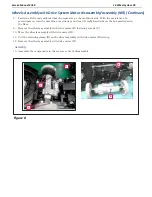
The battery charger and main control board communicate through a dedicated wire. This communication connection allows
the battery charger charging curve to be set directly from the machine dashboard and to view the operational state of the
battery charger during charging directly on the dashboard display. When the charger is plugged into the mains, it checks with
the main controller to find out what type of batteries are installed in the machine so that it can use the correct charging curve.
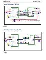
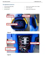
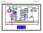
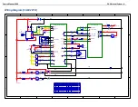
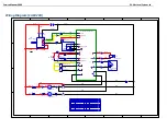
Battery Charger Wiring Diagram
1
1
2
2
3
3
4
4
5
5
6
6
7
7
8
8
D
D
C
C
B
B
A
A
CA60 Electrical Battery Charger Wire Diagram
BAT1
24V
SW4
Key Switch
NC
AC
DC
+
-
NO
CH1
Battery Charger
C1a
C1b
J2-3
J1-15
J1-9
C3
+24V
E1 Main Control Board
Charger IN
COM
RED
BLK
RED
RD/BK
RED
YEL
GRN
RED
BLK
RD/BK
C2
WHI
WHI
J1-3
J1-4
J1-5
C19
C20
GRN YEL
J1-7
B-
B+
F1
Signal Cicuit Fuse
F3
Brush Actuator Fuse(For CA60 20B/24B)
Brush Release Fuse(For CA60 20D/20TD)
Figure 1
Summary of Contents for CA60 20B
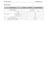
Page 15: ...Service Manual CA60 03 General Information 12 Dimensions Continues CA60 20D CA60 20TD Figure 4...
Page 16: ...Service Manual CA60 03 General Information 13 Dimensions Continues CA60 20B Figure 5...
Page 17: ...Service Manual CA60 03 General Information 14 Dimensions Continues CA60 24B Figure 6...


