


Service Manual-CA60 30 Solution System 43
30 Solution System
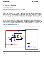
Functional Description
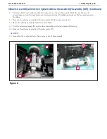
The solution system supplies water and detergent to the brush when cleaning the floor. The solution tank is also the
main machine body. There is a manual valve on the left side of the tank to close the water supply whenever
maintenance must be performed on the machine. The solution flows from the tank to the tap, through the filter and
solenoid valve (EV1) and then to the brush deck.
The detergent pump (M4), present only on EcoFlex systems, controls the flow of detergent from the EcoFlex tank
which is then transported to the flow in the main tube just before the solution enters the brush deck.
The quantity of detergent is defined by the operator via the knob on the Main Control Board (E1).
Located centrally, below the tank, there is also a hole for draining any liquid in the battery compartment.
The solution flow is regulated by various timed ON / OFF cycles according to water flow rate regulation (0 - 4).
Both the solenoid valve and detergent pump (when the EcoFlex system is enabled) follow the same timings.
The solenoid valve and detergent pump operate only with the following inputs/conditions:
Brush function on
One of the two handle switches is pressed
Battery level not in condition with flashing segment
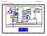
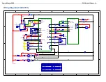
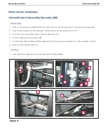
Wiring Diagram(CA60 20B/24B)
1
1
2
2
3
3
4
4
5
5
6
6
7
7
8
8
D
D
C
C
B
B
A
A
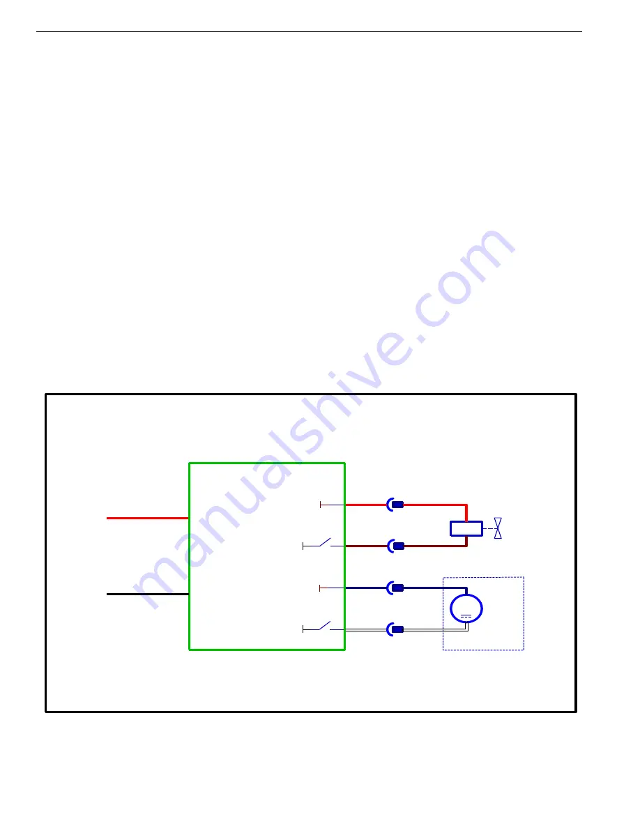
Solution System Wiring Diagram (20B/24B )
E1 Main Control Board
B+
B-
Power
J2-2
+24V
J2-6
J2-5
+24V
J2-1
OPTION
M
M4
Detergent Pump
-
+
C11a
C10a
C11b
C10b
EV1
Solution Valve
B-
B-
Power Supply-
Figure 1
Summary of Contents for CA60 20B
Page 15: ...Service Manual CA60 03 General Information 12 Dimensions Continues CA60 20D CA60 20TD Figure 4...
Page 16: ...Service Manual CA60 03 General Information 13 Dimensions Continues CA60 20B Figure 5...
Page 17: ...Service Manual CA60 03 General Information 14 Dimensions Continues CA60 24B Figure 6...


