4
Parts & Service: 020 8988 7400 / E-mail: Parts@clarkeinternational.com or Service@clarkeinternational.com
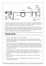
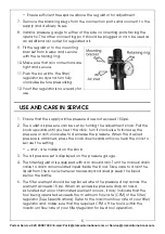
A typical air line layout is shown above. If an automatic in-line filter/regulator is
used it will keep the tool in good condition. The lubricator should be adjusted
to approx 2 drops per minute and SAE 10 oil should be used.
Never exceed the maximum operating pressure for the air tool. Ensure that air
pressure does not exceed that stated in the specification for the air tool when
running. Higher pressures and contaminated air will shorten the life of the air
tool due to faster wear and is a possible safety hazard.
INSTALLATION
1. Shut off the air pressure from the air system.
2. Install the filter/regulator vertically with the bowl vertically down. Ensure
that the filter/regulator is installed with inlet/outlet air flow in the direction of
the arrow on the unit.
3. Note the arrow mark on the regulator body, indicating the direction of air
flow. Connect pipes to the inlet and outlet ports using pipe thread sealant
tape on male threads only. When screwing pipes together, prevent ingress
of shavings and sealant to the interior of the unit. Contamination in the unit
may cause it to fail.
4. The filter/regulator should be installed upstream of any lubricator and
cycling valve(s) in the air line, and should be as close as possible to the air
tools when used as a main line filter/regulator and/or as a final filter/
regulator.
5. The filter/regulator must be installed in such a way that no mechanical
strain occurs.
6. Fit the mounting bracket to a suitable support, situated in line with the
compressed air supply.
Summary of Contents for CAT193
Page 8: ......

