EN
ENGLISH
Clarke
®
Operator's Manual (EN) - CFP Polisher
FORM NO. 70880A - 9 -
4
3
1
5
7
2
6
HOW TO OPERATE THE MACHINE
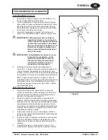
OPERATION (Figure 4)
1
Unwrap the Power Cord (5) and plug it into a properly
grounded outlet.
2
Pull up on the Handle Release Compression Lever (4).
Move the Operator Handle (6) downward until your
arms are almost straight. Push down on the Handle
Release Compression Lever (4) to lock it in place.
3
Lift up on the Operator Handle (6) until the brush (or
pad) is
fl
at against the
fl
oor.
WARNING! Be prepared to control the machine as
soon as the motor starts. Just a slight
up or down movement of the Handle
will make the machine move from side
to side. Raise the Handle to go right.
Lower the Handle to go left.
CAUTION! Immediately start moving the machine
back and forth. Keep the machine
moving while the motor is running to
avoid damage to the
fl
oor or carpet.
4
Hold one of the Operator Hand Grips (1)
fi
rmly, push
the Safety Lock Button (2) and then compress the
Switch Levers (3) to start the motor. NOTE: When the
Switch Levers (3) are released, the machine shuts off
immediately.
NOTE: When spray buf
fi
ng, check the pad every 15
minutes for dirt and wax build-up. If the pad is dirty,
turn it over to expose the clean side or install a clean
pad.
AFTER USE (Figure 4)
1
Place the Operator Handle (6) in the upright position
and unplug the Power Cord (5). Wrap the Power Cord
(5) around the Operator Handle Grips (1) and the Cord
Hook (7).
2
Remove the pad holder or brush from the machine.
Clean the pad or brush and hang it up to dry. Allow
buf
fi
ng pads to dry completely before using again.
Store brushes and pad holders separate from the
machine. Never store the machine with the pad holder
or brush on the machine.
3
Wipe the entire machine with a clean, damp cloth.
Wipe the underside of the brush housing after wet use.
4
Inspect the entire machine and all accessories for
damage. Perform any required maintenance or repairs
before storage.
5
Store the machine in a clean, dry place with the
Operator Handle (6) locked in the upright position.
Figure 4

