background image

9

OPERATION

1. Squeeze the trigger to start the machine.

2. Increase the speed of the machine by increasing pressure on the trigger.

3. Release the trigger to stop.

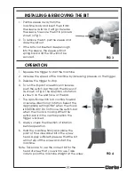
4. To run the impact screwdriver in reverse,

push the switch bar through the drive unit
as shown in Fig 4. The direction of rotation
is shown on the end face of the bar.

The 3-position switch bar controls forward
or reverse direction of rotation. Select the
appropriate setting ONLY when the chuck
is STATIONARY. Do not move the switch-bar
when the chuck is moving. When the
switch-bar is in the central position the
trigger is locked.

5. Always check the direction of rotation

before operation.

6. Hold the machine firmly and place the

point of the screwdriver bit in the screw
head. Apply sufficient pressure that the bit
will not slip off the screw and start the
machine.

Note: Take care to use the correct bit for the

head of screw that you wish to use. Take
care to point the machine straight at the screw.

INSTALLING & REMOVING THE BIT

1. Pull the sleeve away from the

machine body and insert the bit into
the sleeve as far as it will go. Release
the sleeve to secure the bit in place as
shown in Fig 3.

2. To remove the bit, pull the sleeve and

draw the bit out.

If the bit is not inserted deep enough
into the sleeve, the sleeve will not
spring back and the bit will not be
secured.

FIG 3

FIG 4

Summary of Contents for CIS100

Page 1: ...OPERATING MAINTENANCE INSTRUCTIONS GC0309 PROFESSIONAL CORDLESS IMPACT SCREWDRIVER Model CIS100 Part No 4500625 ...

Page 2: ...ered with in any way or not used for the purpose for which it was intended Faulty goods should be returned to their place of purchase no product can be returned to us without prior permission This guarantee does not effect your statutory rights ENVIRONMENTAL PROTECTION Do not dispose of this product with general household waste All tools accessories and packaging should be sorted taken to a recycl...

Page 3: ... Specifications 11 Parts List and Diagram 12 Declaration of Conformity 14 COMPONENT INVENTORY The CIS100 is a professional rechargeable cordless impact screwdriver Upon receipt unpack and lay out the components checking against the following list Any damage or deficiency should be reported to your CLARKE dealer immediately 1 12V Impact screwdriver with 1 7a h battery pack 2 Battery charging unit 3...

Page 4: ... pain occurs and seek medical advice before resuming use 2 ALWAYS use ear defenders 3 ALWAYS stay alert and use common sense do not use this product when you are tired or under the influence of alcohol or medication 4 ALWAYS ensure the workpiece is firmly secured leaving both hands free to control the impact screwdriver 5 ALWAYS wear eye protection when using this product eye protection must provi...

Page 5: ... sharp edges hot surfaces 18 NEVER attempt to wipe the machine clean with solvents Wipe plastic parts with a soft cloth slightly dampened with soapy water 19 NEVER attempt any repairs yourself If you have a problem with this product contact your local CLARKE dealer SAFETY SYMBOLS The full technical specification of the battery charger is printed on a label on the charger The meanings of the markin...

Page 6: ...e non rewireable please note 1 The plug must be thrown away if it is cut from the electric cable There is a danger of electric shock if it is subsequently inserted into a socket outlet 2 Never use the plug without the fuse cover fitted 3 Should you wish to replace the fuse cover ensure that the correct replacement is used as indicated by marking or colour code 4 Replacement fuse covers can be obta...

Page 7: ...e of the battery pack and pull gently down to disengage the battery pack from the machine body as in Fig 1 3 Insert the battery pack into the battery charger as shown in Fig 2 noting that it will only fit one way 4 Plug the charger into a 230v mains power supply and switch ON The green POWER ON light will illuminate with the RED charging light flashing and charging will begin If charging does not ...

Page 8: ...fe we recommend that you maintain the battery in a fully charged state at all times If the battery pack is not to be fitted immediately ensure that the metal contacts are protected so as to avoid the possibility of a short circuit which would cause damage Remember to avoid extremes of heat or cold when charging Avoid temperatures outside the range of Minimum 4 C Maximum 40 C Avoid placing batterie...

Page 9: ...e trigger is locked 5 Always check the direction of rotation before operation 6 Hold the machine firmly and place the point of the screwdriver bit in the screw head Apply sufficient pressure that the bit will not slip off the screw and start the machine Note Take care to use the correct bit for the head of screw that you wish to use Take care to point the machine straight at the screw INSTALLING R...

Page 10: ...d at all times Check the battery charger power cable to ensure it is sound free from cracks etc All bearings in this tool are lubricated with sufficient amount of high quality lubricant for the tool s lifetime under normal operating conditions therefore no further lubrication is required Refer to your Clarke dealer if internal maintenance is required Your Clarke Impact Screwdriver has been designe...

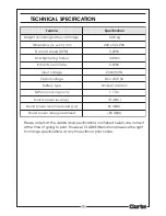
Page 11: ...i e W g k 8 0 2 m m h x w x l s n o i s n e m i D 8 3 2 x 2 6 x 0 0 2 M P R d e e p s d a o l o N 0 0 2 2 0 e u q r o t g n i n e t h g i t x a M m N 8 0 1 e t u n i m r e p s t c a p m I 0 0 9 2 0 e g a t l o v t u p n I z H 0 5 V 0 3 2 e g a t l o v t u p t u O A 5 2 V 4 1 C D e p y t y r e t t a B m u i m d a C l e k c i N y t i c a p a c k c a p y r e t t a B h a 7 1 p L l e v e l r e w o p d ...

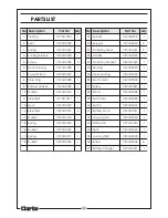
Page 12: ... 0 0 0 1 S I C Z C 1 6 2 r a e G r o t o M 6 2 0 0 1 S I C Z C 1 9 t e k s a G r e b b u R 9 0 0 0 1 S I C Z C 1 7 2 w e r c S 7 2 0 0 1 S I C Z C 1 0 1 t e k s a G 0 1 0 0 1 S I C Z C 1 8 2 r o t o M 8 2 0 0 1 S I C Z C 1 1 1 l l a B l e e t S 1 1 0 0 1 S I C Z C 1 9 2 r a b h c t i w S 9 2 0 0 1 S I C Z C 1 2 1 l i v n A 2 1 0 0 1 S I C Z C 1 0 3 h c t i w S 0 3 0 0 1 S I C Z C 1 3 1 l l a B l e...

Page 13: ...13 PARTS DIAGRAM ...

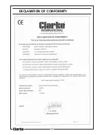
Page 14: ...14 DECLARATION OF CONFORMITY ...

Page 15: ...______________________________ __________________________________________________________________________ __________________________________________________________________________ __________________________________________________________________________ __________________________________________________________________________ _____________________________________________________________________...

Page 16: ......

Reviews: