-9-
16.
All you need to do now is complete your “mirror image” string. The jig makes this very
simple. Remove the sliding bar from the spacers taking care not to move or loosen
them whilst doing so. Refit sliding bar on opposite side of the jig and secure in position
with the wingnuts, again taking care not to loosen or allow the spacers to move. The
jig is now prepared for the opposing string.
17.
Draw the margin along the second string to the same distance as on the first. Next,
position the jig on the string, utilising the sliding bar to achieve the pitch angle and
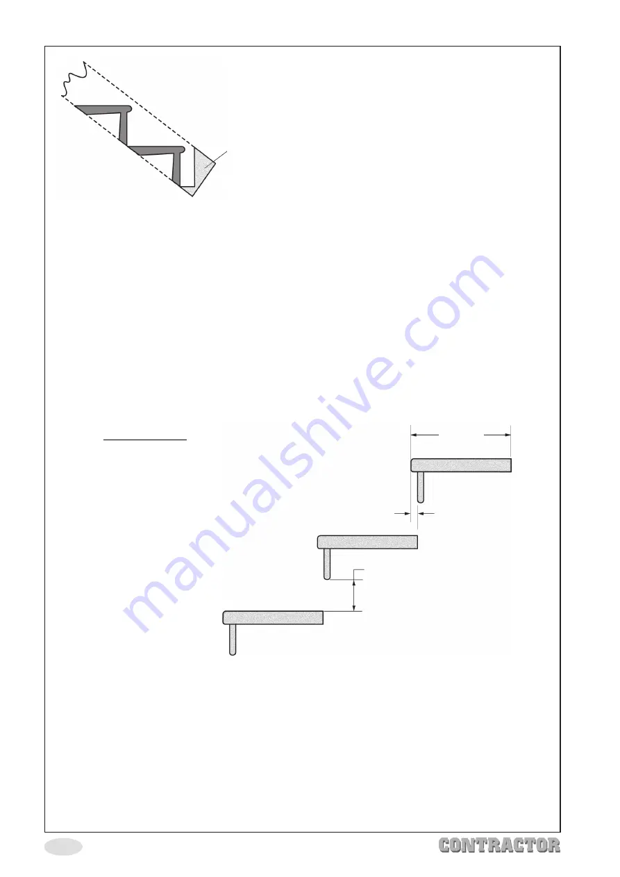
ensuring that the first riser will not break out through the end of the string. See
diagram above. No measuring or calculating is required as the jig transfers all the
required datum information to the second string.
18.
Repeat the succession of risers and treads along the second string in the same
way as the first string, (see point 15
). Please note, you must, of course, use the same
pitch angle line distance as on the first string.
NOTE:
Enough room has to be left on the string before the first
riser is cut to ensure there is no break-out. It is better to
have more material, than not enough as the strings can
be cut to size afterwards.
260mm
15mm Overlap
Gap MUST NOT Exceed 100mm
Open Stair Jig
The open stair jig works very much
in the same way as the closed
staircase, but the risers are left open.
Setting up follows the same
procedure as the closed staircase,
but there are a number of factors,
which the user will have to follow,
to ensure right construction, and to
comply with approved document K
Building Regulations 1985.
♦
A 30mm guide bush is used with a 16mm straight cutter, producing the correct gap
for the riser and tread.
♦
The tread has a fixed length of 260mm, with a thickness of 33mm.
♦
The radius of the base of the riser and the nosing of the tread is set at 8mm.
♦
The nosing on the tread has a fixed projection of 17mm.
♦
The tread should overlap each other by 15mm (see diagram above).
♦
The gap between the base of the riser and the upper face of the tread below should
not exceed 100mm. This is to ensure that a 100mm diameter sphere, the equivalent
of a child’s head, will not pass through the riser (see diagram above).


