background image

-6-

4.

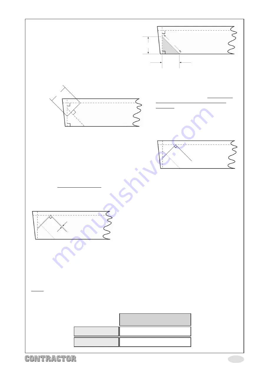
Measure from the right angled line
along the side of the string, the going
length and mark this point. From the
same corner point intersection, measure
across the end along the right angled
line, the rise, and mark this point. Now
draw a line between these two points.
This line creates your pitch angle.
(Measure pitch line and note for point
15 - page 8).

FIRST RISER
AT BASE OF

STAIRS

5

.

To find your start point along the
margin, you need to draw a line at
right angles to this pitch angle line.
This line must be no less than the
length of the rise and must be at
right angles with the pitch line
angles. The intersection of this line
(The first riser line) with the margin
will be your start point and the angle
at which this line is drawn will be the
angle to set the jig.

6.

Finally, mark a line (The first tread line) at right
angles to the first riser line from the
intersection point with the riser and the pitch
line.

Setting Up the Jig

7.

The final thing to calculate is the offset value
between the edge of the cutter and the
edge of the jig cut out.

8.

This offset value varies according to which
tread thickness you require.

9.

Select from the table (page 7) the tread
thickness and nose projection you require. As
a general rule the nose projection equals the
tread thickness. This will tell you which cutter
size to use and the resultant offset value
required to set the jig. Refer back to the table
to determine which guide bush and cutter
to use, before cutting.

10.

Mark the offset value against the first riser and the first tread line as shown in the
diagram above.

NOTE:

If a 30mm guide bush is going to be used instead of the supplied guide bushes,

then refer to table below.

38mm Fixed Nose

Ø16mm Cutter

25.4mm tread - 8mm offset

Ø22mm Cutter

32mm tread - 5mm offset

Pitch Angle Line

Offset Value

Rise

Going

Summary of Contents for CONTRACTOR 6462120

Page 1: ...STAIR JIG Model No CSJ100 Part No 6462120 OPERATION MAINTENANCE INSTRUCTIONS 0405 STAIR JIG ...

Page 2: ... note that the details and specifications contained herein are correct at the time of going to print However CLARKE International reserve the right to change specifications at any time without prior notice 1 ...

Page 3: ...t thought This jig is certainly simpler and more user friendly than anything else currently on the market Check List CLARKE GUARANTEE This CLARKE product is guaranteed against faulty manufacture for a period of 12 months from the date of purchase Please keep your receipt as proof of purchase This guarantee is invalid if the product is found to have been abused or tampered with in any way or not us...

Page 4: ...string is the wooden side support which holds the tread It is either positioned on one or both sides All machining with the router takes place on the string Tread The tread is the wooden part on which you stand on a staircase Riser The riser is the part between each tread See diagram This effects the rise which is measured from the top of the tread to the top of the next tread and every step or la...

Page 5: ... the nosing of one step and the nosing of the step above or as British Standards state face of a riser to face of a riser Like the riser British Standards state strict regulations These are The going should not be less than 220mm for a private stairway and not less than 250mm for a common stairway Pitch line The pitch line is an imaginary line which is drawn from the edge of each tread It stretche...

Page 6: ...repare string for marking out and keep best face upper most It is best to keep any bow in the string towards the top of the stairs 2 A line has to be drawn for a metre or so a certain distance away from the edge of the string The distance is governed by the nose length which will be used To obtain the right distance refer to the table below Rise of flight Rise of step Example 185mm Pitch Line Goin...

Page 7: ...t tread line at right angles to the first riser line from the intersection point with the riser and the pitch line Setting Up the Jig 7 The final thing to calculate is the offset value between the edge of the cutter and the edge of the jig cut out 8 This offset value varies according to which tread thickness you require 9 Select from the table page 7 the tread thickness and nose projection you req...

Page 8: ... steps 1 to 4 below to the relevant slots in the jig push spacers firmly against the edge of the string Ensure an equal amout of the stud is visible on both sides when the spacers are tightened A B Tighten the spacers by turning them in opposing directions until tight hand tight only Fit washer and wingnut on the top two studs and gently tighten Attach the sliding bar to the bottom studs and secur...

Page 9: ...equentially along the string The distance between each movement of the Jig is equal to the length of the pitch angle line See diagram above refer back to page 6 when steps were followed to calculate the pitch angle line and the length measured The angle of the pitch is maintained by the sliding bar mechanism The procedure to follow is to mark a line along the margin where the right hand side of th...

Page 10: ...g NOTE Enough room has to be left on the string before the first riser is cut to ensure there is no break out It is better to have more material than not enough as the strings can be cut to size afterwards 260mm 15mm Overlap Gap MUST NOT Exceed 100mm Open Stair Jig The open stair jig works very much in the same way as the closed staircase but the risers are left open Setting up follows the same pr...

Page 11: ...the pitch angle line and continue to follow steps 5 to 6 on page 6 4 Follow point 10 marking an offset value of 7mm page 6 5 Follow procedure as for the closed stair jig but remembering that the gap between base of riser and upper face of lower tread does not exceed 100mm see diagram above A block spacer can be put in the base of riser aperture on the jig to decrease the length of the riser alteri...

Page 12: ......

Reviews: