background image

3

Parts & Service: 020 8988 7400 / E-mail: Parts@clarkeinternational.com or Service@clarkeinternational.com

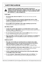
SAFETY PRECAUTIONS

WORK AREA

1.

Keep work area clean and well lit.


Cluttered and dark areas invite 

accidents.

2.

Do not operate power tools in explosive atmospheres, such as in the 
presence of flammable liquids, gases or dust.


Power tools create sparks 

which may ignite the dust or fumes.

3.

Keep children and bystanders away while operating a power tool.


Distractions can cause you to lose control.

ELECTRICAL SAFETY

1.

Avoid body contact with earthed or grounded surfaces such as pipes, 
radiators, ranges or refrigerators.


There is an increased risk of electric shock 

if your body is earthed or grounded.

2.

Do not expose power tools to rain or wet conditions.


Water entering a 

power tool will increase the risk of electric shock.

3.

When operating a power tool outdoors, use an extension cord suitable for 
outdoor use. 

Use of a cord suitable for outdoor use reduces the risk of 

electric shock.

PERSONAL SAFETY

1.

Stay alert, watch what you are doing and use common sense when 
operating a power tool. Do not use a power tool while you are tired or 
under the influence of drugs, alcohol or medication. 

A moment of 

inattention while operating power tools may result in personal injury.

2.

Use safety equipment. Always wear eye protection. 

Safety equipment such 

as dust mask, non-skid safety shoes, or hearing protection used for 
appropriate conditions will reduce personal injuries.

3.

Avoid accidental starting. Ensure the switch is in the off position before 
connecting to the power supply.


4.

Do not overreach. Keep proper footing and balance at all times.


This 

enables better control of the power tool in unexpected situations.

WARNING: READ ALL INSTRUCTIONS. FAILURE TO FOLLOW ALL 
INSTRUCTIONS LISTED BELOW MAY RESULT IN ELECTRIC SHOCK, FIRE AND/
OR SERIOUS INJURY. THE TERM “POWER TOOL” IN ALL WARNINGS LISTED 
BELOW REFERS TO YOUR HAMMER DRILL.

Summary of Contents for Contractor CON1500RDV

Page 1: ...OPERATION MAINTENANCE INSTRUCTIONS LS1215 ROTARY HAMMER DRILL MODEL NO CON1500RDV PART NO 6479605 ...

Page 2: ...he date of purchase Please keep your receipt which will be required as proof of purchase This guarantee is invalid if the product is found to have been abused or tampered with in any way or not used for the purpose for which it was intended Faulty goods should be returned to their place of purchase no product can be returned to us without prior permission This guarantee does not effect your statut...

Page 3: ...oors use an extension cord suitable for outdoor use Use of a cord suitable for outdoor use reduces the risk of electric shock PERSONAL SAFETY 1 Stay alert watch what you are doing and use common sense when operating a power tool Do not use a power tool while you are tired or under the influence of drugs alcohol or medication A moment of inattention while operating power tools may result in persona...

Page 4: ...hildren and do not allow persons unfamiliar with the power tool or these instructions to operate the power tool Power tools are dangerous in the hands of untrained users 5 Maintain power tools Check for misalignment or binding of moving parts breakage of parts and any other condition that may affect the power tools operation If damaged have the power tool repaired before use Many accidents are cau...

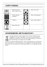
Page 5: ... regulations in relation to the treatment recycling recovery and environmentally sound disposal of the WEEE In effect this means that this product must not be disposed of with general household waste It must be disposed of according to the laws governing Waste Electrical and Electronic Equipment WEEE at a recognised disposal facility Read instruction manual before use Wear dust mask Class 2 Double...

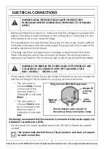
Page 6: ...of this product do not correspond with the markings on the terminals of your plug proceed as follows The wire which is coloured Blue must be connected to the terminal which is marked N or coloured Black The wire which is coloured Brown must be connected to the terminal which is marked L or coloured Red We strongly recommend that this machine is connected to the mains supply via a Residual Current ...

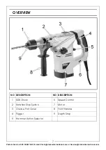
Page 7: ...ts clarkeinternational com or Service clarkeinternational com OVERVIEW NO DESCRIPTION NO DESCRIPTION 1 SDS Chuck 6 Speed Control 2 Rotation Stop Switch 7 Motor 3 Grease Port Cover 8 Front Handle 4 Trigger 9 Depth Stop 5 Hammer Action Selector ...

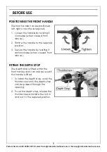
Page 8: ...en viewed from above 2 Rotate the handle to the required position 3 Secure the handle by twisting it anticlockwise when viewed from above FITTING THE DEPTH STOP The depth stop is fitted within the front handle and can only be used if this handle is fitted 1 To install the depth stop undo the thumbscrew until the depth stop can be passed through the opening 2 To set the depth stop release the thumb...

Page 9: ...e the collar to lock in place 3 Check by pulling the bit to see if it is locked in place IMPORTANT Always clean the shaft of the drill bit before inserting into the chuck IMPORTANT Do not allow dust or debris inside the chuck as this will cause problems in the future REMOVING A BIT 1 Slide the collar to the rear and pull the bit out the chuck CAUTION WHEN REMOVING A BIT FROM THE DRILL REMEMBER THA...

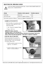
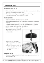
Page 10: ...ssary load on the motor Check the drill bits regularly re sharpen or replace if required ROTATION ON OFF SELECTOR Some jobs require the chuck to remain stationary yet still have the hammer effect such as chiselling concrete plaster etc Set the rotation selector to the right for no rotation Set the rotation selector to the left for normal rotation CAUTION THESE OPERATIONS SHOULD ONLY BE PERFORMED W...

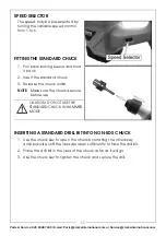
Page 11: ...2 Insert the standard chuck 3 Release the chuck collar NOTE Make sure the chuck is secure before use INSERTING A STANDARD DRILL BIT INTO NON SDS CHUCK 1 Use the chuck key to open the chuck by rotating the chuck key anticlockwise until the jaws are open sufficiently to take the drill bit 2 Place the drill bit in the jaws of the chuck as far as it will go 3 Use the chuck key to tighten the chuck and...

Page 12: ... See page 9 2 If required adjust the front handle for the most comfortable position See page 8 Always hold the drill securely and use the auxiliary handle as shown 3 Set the required operating mode See page 10 4 Set the required speed See page 11 5 When drilling vertically overhead fit the rubber dust collector shown onto the drill bit 6 Position the tool against the surface to be drilled and pull...

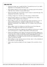
Page 13: ... hot To reduce overheating use a suitable cooling lubricant No cooling lubricant is necessary when drilling cast iron or brass as they should be drilled dry When drilling metal the harder the metal the slower the drill speed Similarly the bigger the drill bit the slower the speed To prevent the drill bit from slipping when starting to drill a hole in metal use a centre punch to make an indentation...

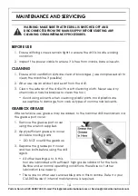
Page 14: ...cs are susceptible to damage from various types of commercial solvents GEARBOX GREASE After extensive use grease may be added to the hammer drill mechanism via the grease port cover 1 Remove the grease port cover using the wrench supplied 2 Apply sufficient grease to cover all visible moving parts DO NOT overfill the gearbox 3 Replace the grease port cover and hex bolts before using the drill agai...

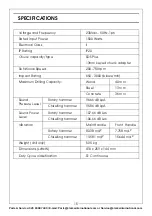
Page 15: ...Speed 200 750 rpm Impact Rating 650 3000 blows min Maximum Drilling Capacity Wood 40 mm Steel 13 mm Concrete 36 mm Sound Pressure Level Rotary hammer 96 66 dB LpA Chiselling hammer 95 86 dB LpA Sound Power Level Rotary hammer 107 66 dB LWA Chiselling hammer 106 66 dB LWA Vibration Main Handle Front Handle Rotary hammer 8 338 m s2 7 758 m s2 Chiselling hammer 19 581 m s2 15 644 m s2 Weight drill on...

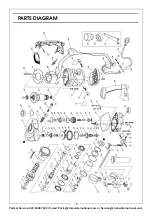
Page 16: ...16 Parts Service 020 8988 7400 E mail Parts clarkeinternational com or Service clarkeinternational com PARTS DIAGRAM ...

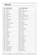
Page 17: ... O Ring 042 Bearing 011 Guard Ring Sleeve 043 Washer 012 Steel Ball 044 Needle Bearing 013 O Ring 045 Core 014 Second Striker 046 Spring 015 O Ring 047 Steel Ball 016 Ram 048 Second Gear 017 Circlip 049 Circlip 018 Grease Seal 050 Washer 019 Washer 051 Circlip 020 Bearing 052 Clutch 021 Steel Ball 053 Disc Spring 022 Cylinder 054 Washer 023 Key 055 Bearing 024 Circlip 056 Crankshaft 025 Bevel Gear...

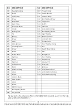
Page 18: ...107 Self tapping Screw 074 Pin 108 Right Handle 075 Spring 109 Speed Control 076 Screw 110 Clamp Collar 077 Knob 111 Thumbscrew 078 Knob Spring 112 Front Handle Clamp 079 Locating Piece 113 Nut 080 Screw 114 Depth Stop Clamp 081 Screw 115 Bolt 082 Switch Knob 116 Straight Pin 083 Bearing 117 Front Handle 084 Rotor 118 Depth Stop 085 Bearing 119 Grease Pot 087 Air Deflector 120 Dust Cap 088 Stator ...

Page 19: ...19 Parts Service 020 8988 7400 E mail Parts clarkeinternational com or Service clarkeinternational com DECLARATION OF CONFORMITY ...

Page 20: ......

Reviews: