background image

5

Parts & Service: 020 8988 7400 / E-mail: Parts@clarkeinternational.com or Service@clarkeinternational.com

f.

Dress properly. 

Do not wear loose clothing or jewellery. Keep your hair, clothing 

and gloves away from moving parts. Loose clothes, jewellery or long hair can be 
caught in moving parts.

4. POWER TOOL USE AND CARE

a.

Do not force the power tool. 

Use the correct power tool for your application. 

The correct power tool will do the job better and safer at the rate which it was 
designed.

b.

Do not use the power tool if the switch does not turn it on and off. 

Any 

power tool that cannot be controlled with the switch is dangerous and must be 
repaired.

c.

Disconnect the plug from the power source before making any 
adjustments, changing accessories, or storing power tools.

 Such 

preventive safety measures reduce the risk of starting the power tool 
accidentally.

d.

Store idle tools out of the reach of children and do not allow persons 
unfamiliar with the power tool or these instructions to operate the power 
tool. 

Power tools are dangerous in the hands of untrained users.

e.

Maintain power tools

. Check for misalignment or binding of moving parts, 

breakage of parts and any other condition that may affect the power tools 
operation. If damaged, have the power tool repaired before use. Many 
accidents are caused by poorly maintained power tools.

f.

Keep cutting tools sharp and clean. 

Poorly maintained cutting tools with 

sharp cutting edges are less likely to bind and are easier to control.

g.

Use the power tool, accessories and tool bits etc., in accordance with 
these instructions

. Use of the power tool for operations different from intended 

could result in a hazardous situation.

5. SERVICE

a.

Have your power tool serviced by a qualified repair person using only 
identical replacement parts. 

This will ensure that the safety of the power tool 

is maintained.

Summary of Contents for Contractor CR3

Page 1: ...OPERATION MAINTENANCE INSTRUCTIONS LS1111 1800W VARIABLE SPEED ROUTER MODEL NO CR3 PART NO 6462081 ...

Page 2: ...eep your receipt which will be required as proof of purchase This guarantee is invalid if the product is found to have been abused or tampered with in any way or not used for the purpose for which it was intended Faulty goods should be returned to their place of purchase no product can be returned to us without prior permission This guarantee does not effect your statutory rights IN THE BOX 1 x Ro...

Page 3: ... OF CONTENTS INTRODUCTION 2 GUARANTEE 2 IN THE BOX 2 TABLE OF CONTENTS 3 GENERAL SAFETY RULES 4 ADDITIONAL WARNINGS FOR ROUTERS 6 ELECTRICAL CONNECTIONS 7 OVERVIEW 8 BEFORE USE 9 OPERATION 10 MAINTENANCE AND CARE 16 ENVIRONMENTAL PROTECTION 16 TROUBLESHOOTING 17 SPECIFICATIONS 18 DECLARATION OF CONFORMITY 19 ...

Page 4: ...d or entangled cords increase the risk of electric shock d When operating a power tool outdoors use an extension cord suitable for outdoor use Use of a cord suitable for outdoor use reduces the risk of electric shock 3 PERSONAL SAFETY a Stay alert watch what you are doing and use common sense when operating a power tool Do not use a power tool while you are tired or under the influence of drugs al...

Page 5: ...ing the power tool accidentally d Store idle tools out of the reach of children and do not allow persons unfamiliar with the power tool or these instructions to operate the power tool Power tools are dangerous in the hands of untrained users e Maintain power tools Check for misalignment or binding of moving parts breakage of parts and any other condition that may affect the power tools operation I...

Page 6: ...nsure it has the right ampere rating for your power tool and is in a safe electrical condition k Always check walls floors and ceilings to avoid hidden power cables and pipes l After long working periods external metal parts and accessories could be hot m Handle router bits with care they can be extremely sharp n Check the bit carefully for signs of damage or cracks before use Replace damaged or c...

Page 7: ...If the colours of the wires in the power cable of this product do not correspond with the markings on the terminals of your plug proceed as follows The wire which is coloured Blue must be connected to the terminal which is marked N or coloured Black The wire which is coloured Brown must be connected to the terminal which is marked L or coloured Red The wire which is coloured Yellow and Green must ...

Page 8: ... NUMBER NO DESCRIPTION PART NUMBER 1 Collet nut ARGCR301 7 Depth Stop Lock ARGCR307 2 Spindle Lock ARGCR302 8 Depth Stop Turret ARGCR308 3 Mains Lead ARGCR303 9 Side Fence ARGCR309 4 Handle ARGCR304 10 Dust Extractor Spout ARGCR310 5 Fine Height Adj ARGCR305 11 Thumb screw ARGCR311 6 Depth Stop Scale ARGCR306 12 Guide Rod ARGCR312 ...

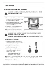
Page 9: ...1 Press and hold the spindle lock whilst rotating the spindle until the spindle locks into position 2 Using the wrench supplied remove the collet nut 3 Carefully remove the collet from the nut and replace with the collet you require Your router is supplied with a selection of collet sleeves NOTE The 12 mm collet can be used with the 6 mm and 8mm collet sleeve NOTE The 12 7 mm collet can be used wi...

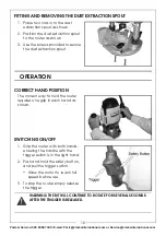
Page 10: ...cure the dust extraction spout OPERATION CORRECT HAND POSITION The correct way to hold the router requires one grip in each hand as shown SWITCHING ON OFF 1 Grip the router with both hands ensuring the handle with the trigger switch is in the right hand 2 Push and hold the safety button and pull the trigger switch Allow the motor to reach full speed before use 3 To stop the router simply release t...

Page 11: ... lowest setting Rotate the turret if required 4 Make a note of the position indicated on the scale 5 Raise the height of the depth stop by the depth you want to cut into the workpiece The scale is marked in mm 6 Tighten the depth stop lock USING THE FINE HEIGHT ADJUSTER 1 Loosen the fine adjustment lock 2 Make the fine adjustments by turning the fine height adjuster 3 Screw the fine adjustment loc...

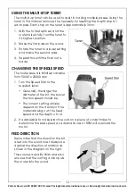
Page 12: ...l the final cut is made CHANGING THE SPINDLE SPEED The router speed is infinitely variable from 9000 to 23000 rpm 1 Turn the Speed Dial to the required level Generally the larger the diameter of the bit the slower the tool speed should be The correct setting will also depend on the density of the material being cut the feed speed and the depth of cut 2 It is advisable to make practice cuts on a pi...

Page 13: ... the speed selected Practice judging the feed speed on scrap timber by listening to the router during use MOULDING NATURAL TIMBERS Always mould the end grain of natural timber first This will ensure that any breakout is removed when the long grain is routed PLUNGE CUTTING 1 Set the required depth of cut See page 11 2 With the motor running press down on the two handles to plunge the bit into the w...

Page 14: ...side fence to the required distance and lock in place using the thumb screws 2 Set the depth of cut See page 11 3 When the router reaches full speed gently lower the bit into the workpiece and lock the plunge lever 4 Move the router along the workpiece maintaining a sideways pressure to ensure the side fence does not come away from the workpiece and downward pressure on the inside hand to prevent ...

Page 15: ...te into position as shown 3 Replace the screws to secure the template guide bush and the dust extraction spout MAKING A TEMPLATE When making templates you must remember to allow for the distance from the edge of the guide bush to the edge of the bit this is known as the offset CALCULATIONS FOR THE TEMPLATE OFFSET The router offset is calculated in the following way The outside diameter of the guid...

Page 16: ... router inspected and maintained by qualified service personnel Do not attempt to repair the router unless you are qualified to do so STORAGE Make sure that the router has been thoroughly cleaned before storing it in a clean dry place out of the reach of children LUBRICATION The bearings of the machine do not need lubrication as they are sealed The two plunge columns on the routing base should be ...

Page 17: ...ice department 0208 988 7400 Router runs slowly Blunt or damaged bit Re sharpen or replace bit Variable speed set low Increase variable speed setting Motor is overloaded Reduce pressure on router Makes an unusual sound Mechanical obstruction Contact the CLARKE service department 0208 988 7400 Armature has shorted sections Contact the CLARKE service department 0208 988 7400 Excessive vibration Bent...

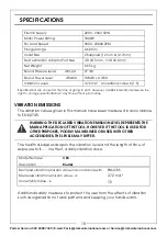
Page 18: ...on such as organization of work patterns and keeping your hands warm Electric Supply 220V 230V 50Hz Motor Power Rating 1800W No Load Speed 9000 23000 RPM Plunge Range 0 60 mm Collet Size 2 Supplied 12 mm 12 7mm Dust extraction Adaptor Port Size I D 34 5 mm O D 39 0 mm Net Weight 6 65 kg Sound Pressure level dB LpA 97 dB Sound Power level dB LWA 108 dB 3 dBA Vibration Levels 3 72 m s2 Uncertainty v...

Page 19: ...19 Parts Service 020 8988 7400 E mail Parts clarkeinternational com or Service clarkeinternational com DECLARATION OF CONFORMITY ...

Page 20: ......

Reviews: