background image

15

Parts & Service: 020 8988 7400 / E-mail: Parts@clarkeinternational.com or Service@clarkeinternational.com

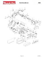
COMPONENT PARTS LIST

CONSUMABLE ITEMS

Replacement Foam Polishing Sponges, Polishing Bonnets and Sanding Discs 
(Grit 40, 60, 80) are available from your Clarke dealer.

No

Description

No

Description

1

Backing disc

22

Screw ST3.9x60

2

Screw M5 x 8

23

Stator

3

Spindle II

24

608 bearing cover

4

Bearing 6001-2RS

25

Main housing

5

Lock Spring 12

26

Carbon brush holder

6

Energy block

27

Disc spring

7

Cover

28

Carbon brush

8

Screw M4 x 14

29

Speed adjuster

9

Front cover

30

Right casing

10

Spindle

31

Screw ST3.9x14

11

Woodruff key 3x 10

32

Strain relief

12

Large gear

33

Cable gland

13

Needle bearing HK0810

34

Power cable

14

Gearbox cover

35

Capacitor

15

Screw ST3.9x25

36

Switch

16

Gearbox

37

Left casing

17

Lock spring 10

38

Handle

18

Bearing 6000-2RS

39

Screw

19

Rotor

40

Spanner

20

Bearing 627-2Z

41

Screw M8x20

21

Draft shield

42

Allen key

Summary of Contents for CP150

Page 1: ...OPERATION MAINTENANCE INSTRUCTIONS GC0719 ISS 1 ORIGINAL INSTRUCTIONS 150mm 6 ORBITAL SANDER POLISHER MODEL NO CP150 PART NO 6462101 ...

Page 2: ... CLARKE dealer GUARANTEE This product is guaranteed against faulty manufacture for a period of 12 months from the date of purchase Please keep your receipt which will be required as proof of purchase This guarantee is invalid if the product is found to have been abused or tampered with in any way or not used for the purpose for which it was intended Faulty goods should be returned to their place o...

Page 3: ...l reduce risk of electric shock 2 Avoid body contact with earthed or grounded surfaces such as pipes radiators ranges and refrigerators There is an increased risk of electric shock if your body is earthed or grounded 3 Do not expose power tools to rain or wet conditions Water entering a power tool will increase the risk of electric shock 4 Do not abuse the power cable Never use the cable for carry...

Page 4: ...enables better control of the power tool in unexpected situations 6 Dress properly Do not wear loose clothing or jewellery Keep your hair clothing and gloves away from moving parts Loose clothes jewellery or long hair can be caught in moving parts 7 If devices are provided for the connection of dust extraction and collection facilities ensure these are connected and properly used Use of dust colle...

Page 5: ... accidents are caused by poorly maintained power tools 6 Keep cutting tools sharp and clean Properly maintained cutting tools with sharp cutting edges are less likely to bind and are easier to control 7 Use the power tool accessories and tool bits etc in accordance with these instructions taking into account the working conditions and the work to be performed Use of the power tool for operations d...

Page 6: ...ins supply via a Residual Current Device RCD If in doubt consult a qualified electrician DO NOT attempt any repairs yourself This symbol indicates that this is a Class II product and does not require an earth connection EXTENSION CABLES Always use an approved cable extension suitable for the power rating of this tool see specifications the conductor size should also be at least the same size as th...

Page 7: ... for damage or shortages etc Any found should be reported to your CLARKE dealer where the machine was originally purchased NO DESCRIPTION NO DESCRIPTION 1 D Handle 6 14 mm Spanner 2 Handle Fixing Bolts 7 6 mm Hexagon Key 3 150 mm Backing Disc 8 Trigger 4 150 mm Sponge Pad 9 Trigger Lock Button 5 Polishing Bonnet 10 Speed Controller ...

Page 8: ...itted to the backing disc MOUNTING OF ACCESSORIES 1 Press either the sponge pad or polishing bonnet onto the hook eye covered backing disc Peel the sponge pad or polishing bonnet off the hook and eye surface to remove from the backing pad 2 Before using the machine ensure that the backing disc and accessory are correctly mounted and firmly tightened 3 Check that the backing disc and accessory runs...

Page 9: ...d hold the trigger lock button whilst holding the trigger in and the machine will run continuously The machine will continue to run even if the trigger is released 2 To release the trigger lock button squeeze the trigger then release and the motor will stop 3 Slowly apply the machine to the workpiece and proceed to sand or polish Move the disc across the work applying a light even pressure 4 If it...

Page 10: ...ed air 2 Check the power cable to ensure it is sound and free from cracks bare wires etc Avoid using solvents when cleaning plastic parts most plastics are susceptible to damage from the various types of commercial solvents 3 All bearings etc in this machine are lubricated with sufficient high grade lubricant for the machine s lifetime under normal operating conditions therefore no further lubrica...

Page 11: ...ken Consult your Clarke dealer Heavy internal sparking Faulty motor Consult your Clarke dealer Motor becomes hot Unduly heavy use Reduce the force applied to the machine Let the machine do the work Air vents have become blocked Clean out the air vents using compressed air or clean with a dry cloth Use PPE when working with compressed air Low supply voltage Ensure supply voltage is correct If an ex...

Page 12: ...cifications at any time without prior notice Item Specification Dimensions L x W x H 400 x 120 x 100 mm Weight 2 6 kg Backing pad type Polymer with hook loop system Disc Diameter 150 mm Operating voltage Frequency 230V 50 Hz Orbit pitch circle diameter 21 mm Fuse Rating 13 A Motor Power 900 W No Load Speed 0 6000 rpm Sound Pressure Level dB LWA 80 27 dB Guaranteed Sound Power Level dB LWA 91 27 dB...

Page 13: ...13 Parts Service 020 8988 7400 E mail Parts clarkeinternational com or Service clarkeinternational com DECLARATION OF CONFORMITY ...

Page 14: ...14 Parts Service 020 8988 7400 E mail Parts clarkeinternational com or Service clarkeinternational com PARTS LIST DIAGRAM ...

Page 15: ...608 bearing cover 4 Bearing 6001 2RS 25 Main housing 5 Lock Spring 12 26 Carbon brush holder 6 Energy block 27 Disc spring 7 Cover 28 Carbon brush 8 Screw M4 x 14 29 Speed adjuster 9 Front cover 30 Right casing 10 Spindle 31 Screw ST3 9x14 11 Woodruff key 3x 10 32 Strain relief 12 Large gear 33 Cable gland 13 Needle bearing HK0810 34 Power cable 14 Gearbox cover 35 Capacitor 15 Screw ST3 9x25 36 S...

Page 16: ......

Reviews: