background image

7

Parts & Service: 020 8988 7400 / E-mail: Parts@clarkeinternational.com or Service@clarkeinternational.com

ASSEMBLY 

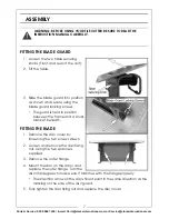
FITTING THE BLADE GUARD

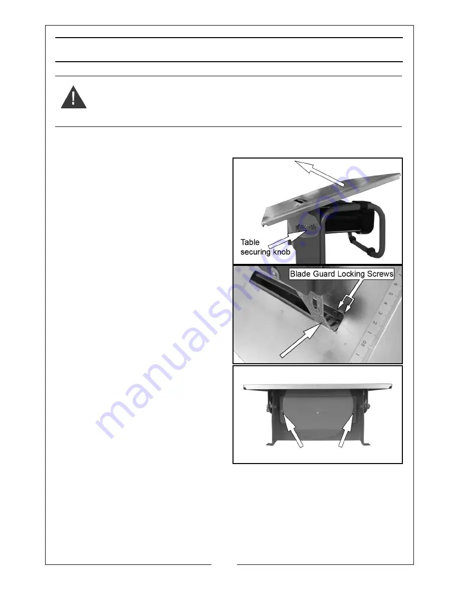
1. Loosen the two table securing 

knobs (Front and rear of the unit).

2. Tilt the table.

3. Slide the blade guard into position 

as shown and secure using the 
blade guard locking screws.

• The guard is held in position 

between the frame and a small 
bracket beneath.

FITTING THE BLADE

1. Remove the disc cover by 

loosening the two screws shown.

2. Loosen and remove the disc fixing 

nut. Using the two spanners 
supplied.

3. Remove the outer flange. 

4. Mount the disc on the arbor and 

replace the outer flange. Turn the 
disc 360 degrees to make sure it matches with the flange properly. 

• The direction arrow on the disc should point in the same direction as the 

marking on the side of the disc guard.

5. Fully tighten the disc fixing nut and replace the disc cover.

WARNING: BEFORE USING YOUR TILE CUTTER BE SURE TO READ THE 
INSTRUCTION MANUAL CAREFULLY.

Summary of Contents for ETC8

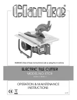
Page 1: ...WARNING Read these instructions before using the machine OPERATION MAINTENANCE INSTRUCTIONS LS0711 ELECTRIC TILE CUTTER MODEL NO ETC8 PART NO 3400515...

Page 2: ...st faulty manufacture for a period of 12 months from the date of purchase Please keep your receipt as proof of purchase This guarantee is invalid if the product is found to have been abused or tampere...

Page 3: ...use an extension cord suitable for outdoor use Use of a cord suitable for outdoor use reduces the risk of electric shock PERSONAL SAFETY 1 Stay alert watch what you are doing and use common sense when...

Page 4: ...ls are dangerous in the hands of untrained users 5 Maintain power tools Check for misalignment or binding of moving parts breakage of parts and any other condition that may affect the power tools oper...

Page 5: ...Never cut more than one tile at a time 10 Never cut pieces too small to be held securely against the side fence without leaving enough space for the hand to be a safe distance from the disc 11 Ensure...

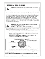
Page 6: ...zard If the colours of the wires in the power cable of this product do not correspond with the markings on the terminals of your plug proceed as follows The wire which is coloured Blue must be connect...

Page 7: ...beneath FITTING THE BLADE 1 Remove the disc cover by loosening the two screws shown 2 Loosen and remove the disc fixing nut Using the two spanners supplied 3 Remove the outer flange 4 Mount the disc...

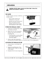
Page 8: ...the parallel guide on the work table as shown 2 Align the hole in the fixing plate with the hole in the end of the parallel guide The fixing plate should be fitted on the inside surface of the work ta...

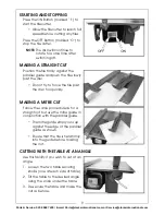
Page 9: ...and push the tile slowly past the disc Do not try to force the tile past the disc too quickly MAKING A MITRE CUT Follow the same procedure as for a straight cut but use the mitre guide in conjunction...

Page 10: ...loosening the two screws shown 3 Loosen and remove the disc fixing nut Using the two spanners supplied 4 Remove the outer flange and the disc clean any dust and debris from the arbor and disc securing...

Page 11: ...11 Parts Service 020 8988 7400 E mail Parts clarkeinternational com or Service clarkeinternational com DECLARATION OF CONFORMITY...

Page 12: ......

Reviews: