background image

Clarke

®

  Operator's  Manual  -  BOOST  28

                                              Page  -53-

Clarke

®

Electrical Schematic  9/05

Summary of Contents for Focus II Mid-Size Autoscrubber Boost 28

Page 1: ...uld occur as well You must have training in the operation of this machine before using it If operator s cannot read this manual have it explained fully before attempting to operate this machine Si Ud...

Page 2: ...51 Connection Diagram 52 Electrical Schematic 53 Operator Safety Instructions 3 Introduction Machine Specifications 5 Procedures for Transporting Machine 6 Symbols Used on Boost 28 8 Machine Control P...

Page 3: ...olvents thinners or other flammable materials This machine is not suitable for picking up hazardous dust Use only commercially available floor cleaning waxes intended for machine operation DANGER Lead...

Page 4: ...oor surfaces can be slippery Water solutions or cleaning materials used with this type of machine can leave wet areas on the floor surface These areas can cause a dangerous condition for the operator...

Page 5: ...l lever style operation Cleaning Swath 28 inches 71 cm Motor Brush 3 4 hp 0 56 KW Brush Pad Size 14 x 28 35 6 cm x 71 cm Brush Speed 2250RPM Brush Pressure 100 lbs 45 4 kg Drive Wheels 2 8 in x 2 in 2...

Page 6: ...ve this machine only on a level surface When you stop the machine put all switches into their OFF position 1 Make sure the loading ramp is at least eight 8 feet 2 5m long and a minimum of 32 0 8m wide...

Page 7: ...8m wide and strong enough to support the machine 3 Make sure the ramp is clean and dry 4 Put the ramp in position 5 Unfasten the machine WARNING The machine is heavy Make sure you use two able persons...

Page 8: ...age 8 Clarke Operator s Manual BOOST 28 SYMBOLS USED ON BOOST 28 Solution Control BrushUp Down Warning Label with parking brake Warning Power Traverse Speed Control Warning Label without parking brake...

Page 9: ...wn position Brush Motor and solution flow will activate when the traverse buttons are pushed To shut brush motor off place brush position switch in up position Key Switch See Figure 3 Item A The key s...

Page 10: ...ult from foam Parking Brake Optional See Figure 7 NOTE Parking Brake must be used if operating machine on greater than 2 gradient Theparkingbrakepreventsmovementofthemachine CAUTION Do not activate th...

Page 11: ...m mainte nance on the machine while the recovery tank is in the intermediate position The tank can be acciden tally bumped and it may slam shut 4 Place the batteries in the tray as shown in figure 8C...

Page 12: ...TION Machine damage and discharge across the tops of the batteries can occur if the batteries are over filled Do not fill the batteries up to the bottom of the tube in each cell Wipe any acid from the...

Page 13: ...3 Put the charger on a flat surface Make sure the vents on the sides are at least two inches away from walls and other objects Make sure there are no objects near the vents on the bottom of the charge...

Page 14: ...overy tank is in the open position The tank can be accidentally bumped and it may slam shut 3 Connect the battery charger AC cord located at the rear ofthemachinetoa15amp min 120Vproperlygrounded wall...

Page 15: ...re13 NOTE When using a black pad position pad on head Lowerheadandoperatemomentarilytoaffixpad topaddriver ifyouhavedifficulty positionpadon floor and lower head then operate How To Remove The Brush O...

Page 16: ...ontinue to run with the squeegee off the floor to avoid drips and also allows you to back up the machine How To Fill The Solution Tank The solution tank can be filled in the front or through the clear...

Page 17: ...in a straight direction forward and backward 2 Stop the machine safely 3 Turn the machine both left and right and return to a straight direction To move the machine follow this procedure 1 Release th...

Page 18: ...position 7 Turn the solution knob to the right to activate the flow of solution Adjust the flow of clean solution to the flow desired 8 Move the machine across the floor in the forward direction 9 Ma...

Page 19: ...nnect the plug on the battery charger from the battery pack connector if using a remote charger 4 Join the connector from the batteries to the control panel cable connection remote charger only See fi...

Page 20: ...sure waterhosetoflushthetankorhose Putthewaterhose into the drain hose 4 Leavethetanksandtherecoverydrainvalveopentodry in the air 5 Check the squeegee blade Use a cloth to clean the squeegee blade If...

Page 21: ...ne WARNING Always wear eye protection and protective clothing when working near batteries NO SMOKING 1 To inspect batteries tip up recovery tank until it locks in thefullopenposition Seefigure27A Tocl...

Page 22: ...queegee Tilt The tilt of the squeegee causes the rear blade to raise up in the center or on the ends depending on which direction the tilt is changed For tilt adjustment refer to figure 30 Loosen left...

Page 23: ...d remove the key 4 Tipuptherecoverytankuntilitlocksinthefullopen position 5 Go to the front of the machine and unlatch the front coverandswingcoveropen 6 Locate the four mounting studs on the brush he...

Page 24: ...0070A Hour Meter Kit 10656A Soft Caster Assembly 51092A Kit Solution Fill 10177A ESP Recycle System 10663A Brushes and Pads Size Description Part No 14 x 28 Red 5 pack 997001 14 x 28 Black 5 pack 9970...

Page 25: ...e batteries for a full 16 hour charge Have an authorized service person repair the charger Check voltage of each cell while discharging Connect the batteries Adjust Pressure PROBLEM CAUSE ACTION The s...

Page 26: ...ch is off Batteries are unplugged Battery terminals are dirty Batteries are discharged Reset the circuit breaker Turn key or switch on Check the battery connections Check battery gauge and recharge NO...

Page 27: ...Clarke Operator s Manual BOOST 28 Page 27 Section II Parts and Service Manual 71071A U S PatentNo 6 105 192 No 6 557 207 No 6 760 947 No 5 383 251 andpatentspending...

Page 28: ...Manual BOOST 28 1 2 3 4 5 6 4 15 8 9 8 10 11 7 8 10 11 12 13 14 8 10 11 16 17 18 9 8 19 21 23 22 20 24 25 27 28 26 31 29 27 32 30 Clarke Final Assembly Drawing 9 05 On BoardChargerOption 15 4 5 6 37...

Page 29: ...5 32 x 9 16 2 2 24 Ref Assembly Solution Tank Ref Ref 25 40136A Battery 6V 250 AH wet Stud Post 4 4 40137A Battery 6V 250 AH dry Stud Post 4 4 891384 Battery 6V 330 AH wet UT Post 4 4 891385 Battery 6...

Page 30: ...l BOOST 28 1 2 3 4 5 6 7 8A 8B 8 9 10 43 40 39 38 37 36 35 34 20 33 18 7 30 32 29 26 25 27 28 24 23 22 31 21 17 18 16 16 19 15 14 13 12 11 40RecommendedTorque 175 or 5 inch pounds 43 41 42 Clarke Reco...

Page 31: ...din8A 2 18 41809A Contact included in 8A 4 19 82100A Nut Strain Relief Lock 1 20 872010 Clamp Hose 1 21 35165A Hose Drain 1 22 832002 Clamp Hose 1 23 839401 Valve Drain 1 24 962943 Screw 8 18 x PN 1 2...

Page 32: ...Page 32 Clarke Operator s Manual BOOST 28 18 19 20 21 25 23 24 1 2 3 4 5 6 5 7 12 5 11 5 15 16 17 8 Clarke Solution Tank Assembly 9 05...

Page 33: ...ESNA SS 1 16 50966A Latch 1 17 80105A Screw 8 32 x 1 SS 2 18 50963B Screen Fill with hose retention 1 51308B Strainer withouthoseretention 1 19 69879A Bracket Latch 1 20 170892 Washer Lock 2 21 170915...

Page 34: ...Operator s Manual BOOST 28 1 2 1 2 3 4 5 6 7 8 9 10 12 13 14 16 17 16 15 18 21 20 19 23 2 22 24 25 26 27 3 28 29 6 9 10 31 9 10 33 34 32 35 30 11 10 15 3 11 36 Clarke Rear Panel Assembly Drawing 9 05...

Page 35: ...360 Spring 1 18 64901A Lever SqueegeeLift 1 19 64490A Handle Squeegee 1 20 980666 Washer 3 8 Starlock 1 21 85389A Screw 3 8 16 x 5 8 1 22 68643A Plate Vacuum Wear 1 23 962968 Screw 10 24 x 2 24 61260A...

Page 36: ...nual BOOST 28 1 2 1 2 3 4 5 6 7 8 9 10 12 13 14 16 17 16 15 18 21 20 19 23 2 22 24 25 26 27 40 29 28 23 9 10 31 9 10 33 34 32 35 30 11 39 15 3 38 37 2 11 41 27 41 42 41 36 Clarke Rear Panel Assembly D...

Page 37: ...666 Washer 3 8 Starlock 1 21 85389A Screw 3 8 16 x 5 8 1 22 61781A Plate Vacuum Wear 1 23 962968 Screw 10 24 x 6 24 61260A Plate Squeegee Lift 1 25 47388A Switch VacuumLever 1 26 85601A Screw 6 32 x 1...

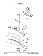
Page 38: ...rke Operator s Manual BOOST 28 1 2 3 4 5 6 7 8 11 12 10 11 14 19 18 1516 1516 3 17 15 15 16 16 20 24 23 21 5 2 25 26 27 28 29 7 27 34 35 36 37 36 33 32 31 38 5 39 30 9 Clarke Control Panel Assembly Dr...

Page 39: ...e 1 15 980603 Washer 4 16 920224 Nut 10 32 Hex 4 17 30072A ControlHandle 18 85391A Screw 20 x 1 2 SS Ref 19 87026A Washer SS Ref 20 40858A Control Solution 1 21 41422A Breaker Circuit25AmpTraverse 1 2...

Page 40: ...1 10 3 4 5 6 6 8 7 9 8 2 15 16 15 11 18 13 14 12 22 17 19 21 20 15 Clarke Squeegee Lift Assembly Drawing 9 05 Page 40 Clarke Operator s Manual BOOST 28...

Page 41: ...ut 20 2 10 81111A Nut 3 8 16 ESNA 1 11 80101A Screw 20 x 3 SS 1 12 85811A Screw 5 16 18 x 1 13 67867A Nut spacer 1 14 60256A Squeegee PivotArm 1 15 81104A Nut Nylock 5 16 60255A Bracket Squeegee 1 17...

Page 42: ...Page 42 Clarke Operator s Manual BOOST 28 1 2 21 21 3 4 5 4 5 20 19 18 7 8 17 21 9 10 11 12 13 14 15 16 22 Clarke Squeegee Assembly Drawing 9 05...

Page 43: ...Wheel Guide 4 Inch Diameter 2 9 60272A Channel SqueegeeWeldment39 1 10 50835A Latch SqueegeeClamp 1 11 930086 Rivet 3 16 x 450 Aluminum 2 12 60252A Strap Clamp SqueegeeRetainer39 1 13 30069A Blade Rea...

Page 44: ...22 1 2 3 4 5 6 22 16 29 16 22 31 28 27 26 25 24 21 23 32 19 7 4 3 2 8 9 10 11 13 11 13 30 8 18 19 Clarke Frame Axle Assembly Drawing 9 05 Page 44 Clarke Operator s Manual BOOST 28...

Page 45: ...3A Ring SnapRetainer 2 15 87616A Washer Nylon 2 16 980205 Washer 5 16 Fender 2 17 962620 Screw 5 16 24 x 2 18 87026A Washer Flat SS 8 19 81104A Nut 20 ESNA SS 9 21 77267A Label TieDown 4 22 980614 Was...

Page 46: ...Clarke Brush Head Assembly Parts List 9 05 Page 46 Clarke Operator s Manual BOOST 28 55 56...

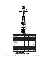
Page 47: ...tainer Eccentric 1 27 61729A Plate Upper 28 1 28 61731A Arm Lift Left 1 29 61732A Arm Lift Right 1 30 61733A Bracker Lift 2 31 61750A RodLift 1 32 61753A Eccentric 1 33 61775A Retainer Bearing 1 34 61...

Page 48: ...o Motor Shaft 8 10160A Brake Asm 24V 1 NOTE Only use spacer ref 2 on transaxles that have a circular step and mounting nuts protruding from end of motor The motor that uses the spacer can be identifie...

Page 49: ...2 NEOPRENEWASHER 1 59803A 59803A 13 FAN END BRACKET 1 14 SPACER 1 15 FAN 1 50997A 50997A 16 ROTATING FAN 1 53914A 17 SPACER 2 50999A 1 50999A 18 STATIONARY FAN 1 51043A 51043A 19 ROTATING FAN 1 51044A...

Page 50: ...Page 50 Clarke Operator s Manual BOOST 28 Clarke Transaxle Drawing 9 05...

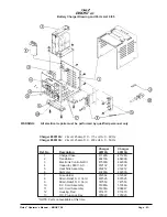
Page 51: ...912382 912382 8 Strain Relief A C Cord 837525 837525 9 Strain Relief D C Cord 747553 747553 10 D C Cord Assembly 51986A 51986A 11 A C Cord Assembly 51974A 908947 12 Housing Red 911470 911470 13 D C Pl...

Page 52: ...Page 52 Clarke Operator s Manual BOOST 28 Clarke Connection Diagram 9 05...

Page 53: ...Clarke Operator s Manual BOOST 28 Page 53 Clarke Electrical Schematic 9 05...

Page 54: ...Page 54 Clarke Operator s Manual BOOST 28 NOTES...

Page 55: ...verige AB Molndal Sweden Aminogatan 18 Box 4029 S 431 04 Molndal 46 31 706 73 00 ALTO Norge A S Oslo Norway Bjornerudveien 24 N 1266 47 2275 1770 U S A Locations European Locations CORPO PRODUCTION FA...

Page 56: ...ice plus transportation costs Warranty is rendered null and void if battery is not kept filled to the proper level with DISTILLED WATER CLARKE POLYDUR AUTOMATIC SCRUBBER SOLUTION AND RECOVERY TANK EIG...

Reviews: