background image


Operation and Maintenance 

Instructions Manual


LC2A Lombardini Engines 

FOR 

FIRE PUMP APPLICATIONS 


Clarke UK, Ltd. 

Unit 1, Grange Works 

Lomond Road 

Coatbridge 

ML5 2NN 

United Kingdom 

TELE: +44(0)1236 429946 

FAX:  +44(0)1236 42274 


www.clarkefire.com 


C132183 rev C 06/14


Summary of Contents for LC2A

Page 1: ...structions Manual LC2A Lombardini Engines FOR FIRE PUMP APPLICATIONS Clarke UK Ltd Unit 1 Grange Works Lomond Road Coatbridge ML5 2NN United Kingdom TELE 44 0 1236 429946 FAX 44 0 1236 42274 www clarkefire com C132183 rev C 06 14 ...

Page 2: ... Start Engine 9 2 6 3 To Stop Engine 10 3 0 ENGINE SYSTEMS 10 3 1 FUEL SYSTEM 10 3 1 1 Bleeding the Fuel System 10 3 1 2 Changing Fuel Filter 10 3 1 3 Fuel Tanks 10 3 2 AIR EXHAUST SYSTEM 10 3 2 1 Ambient Conditions 10 3 2 2 Ventilation 10 3 2 3 Standard Air Cleaner 10 3 2 4 Crankcase Ventilation 10 3 2 4 1 Open Crankcase Ventilation 10 3 2 5 Exhaust System 11 3 3 LUBRICATION SYSTEM 11 3 3 1 Check...

Page 3: ...DATA 14 10 0 WIRING DIAGRAMS 14 11 0 PARTS ILLLUSTRATION 14 NOTE The information contained in this book is intended to assist operating personnel by providing information on the characteristics of the purchased equipment It does not relieve the user of their responsibility of using accepted practices in the installation operation and maintenance of the equipment NOTE CLARKE FPPG Reserves the right...

Page 4: ...imum of hour per week 1 1 IDENTIFICATION NAMEPLATE Throughout this manual the terms Engine and Machine are used The term Engine refers solely to the diesel engine driver as supplied by CLARKE The term Machine refers to any piece of equipment with which the engine might interface This manual provides all the information necessary to operate your newly acquired engine safely and efficiently and perf...

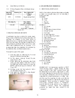
Page 5: ...e equipment to be applied to the points specially provided as shown on the appropriate Engine Installation Drawing Engine weights are shown in figure 2 ENGINE MODEL WEIGHT kg lbs LC2A LP 30 104 229 LC2A LP60 151 333 Figure 2 Figure 3 shows the typical lifting arrangement of a bare engine Note the lifting points on the engine are for lifting the engine only Caution when lifting lift point should al...

Page 6: ...mful gases noise and vibration and it is necessary to take suitable precautionary measures when moving installing and operating the engine to reduce risk associated with the characteristics stated above 4 The engine must be installed in accordance with local laws and regulations The engine must not be started and operated before the machinery into which it is to be incorporated and or its overall ...

Page 7: ...caused by battery acid lubricating oil and diesel fuel Wash the eye with running water for at least 20 minutes keeping the eyelids open so that the water runs over the eyeball and moving the eye in all directions ELECTROCUTION Electrocution can be caused by 1 The engine s electrical system 12 24 VDC 2 The electrical coolant pre heating system 120 240 Volt AC if supplied AC current In the first cas...

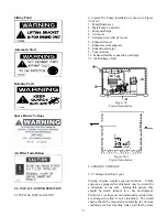
Page 8: ...e base 10 Exhaust flexible connection joint pipe 11 Air Discharge Duct Figure 6 Typical Installation Figure 6A Typical Installation 2 2 ENGINE STORAGE 2 2 1 Storage less than 1 year Storing engines requires special attention Clarke engines as prepared for shipment may be stored for a minimum of one year During this period they should be stored indoors in a dry environment Protective coverings are ...

Page 9: ... associated with the cooling exhaust induction air and fuel systems This section of the manual should be read in conjunction with the relevant Installation and Operation Data Sheets If there is any doubt about an installation contact should be made with Clarke Customer Support giving exact details of the problem All installations should be clean free of any debris and dry Care should be taken to e...

Page 10: ... designed to operate at rated load conditions For testing purposes the engine can be run at lower load lower flow conditions Running times in any one period should not exceed 30 minutes maximum Before starting the engine make sure of the following 1 The operator has free access to stop the engine in an emergency 2 The plant room ventilation ducts are open and the engine has good access for air 3 A...

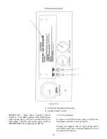
Page 11: ... starts or release after 15 seconds If unit fails to start wait for 10 seconds use MANUAL CRANK 2 and repeat step If COOLING WATER is not flowing or engine oil TEMPERATURE is too HIGH open cooling system manual by pass valve ...

Page 12: ...ting from engine gauge panel Be sure to return selector on main pump controller and engine gauge panel to AUTOMATIC after completing manual run 2 6 3 To Stop Engine If engine is started from main pump controller use main pump controller to stop the engine Engines not equipped with an engine gauge panel and LPCB engine have a manual shutdown lever on the engine for shutdown ...

Page 13: ...condensation to a minimum Open drain at the bottom of the fuel tank once a week to drain off any possible water and or sediment Fill tank after each test run 3 2 AIR EXHAUST SYSTEM 3 2 1 Ambient Conditions Clarke engines are tested in accordance with SAE J1349 Clarke USA or ISO 3046 Clarke UK In this capacity they may be derated to meet certain site conditions failure to do so can seriously impede...

Page 14: ...dipstick with new and clean lubricating oil of an approved grade Fit the drain plug tighten the plug to 34 Nm 25lbf ft 3 5 kgf m 4 Return the unit back into service by returning the AEC selector to automatic position and the manual operating lever to manual stop position 5 Dispose used oil properly 3 3 3 Changing Oil Filter 1 Turn engine off 2 Put a tray under the filter to retain spilt lubricatin...

Page 15: ...p engine by following To Stop Engine Procedure in this manual Figure 38 4 0 MAINTENANCE SCHEDULE 4 1 ROUTINE MAINTENANCE NOTE The following Routine Maintenance schedule is based on an engine usage rate not exceeding 2 hours per month LEGEND Check Clean Replace o Lubricate WEEKLY Air Cleaner Battery Cooling Water Solenoid Valve Exhaust System Fuel Tank General Inspection Governor Run Stop Control S...

Page 16: ... of 12 months beginning at the Start up date of the fire pump system The warranty coverage includes replacement of the part and reasonable cost of labor for installation Components failed due to improper engine installation transportation damage or misuse is not covered under this warranty For additional warranty details see the specific warranty statement John Deere New Engine Warranty on the fol...

Page 17: ...ardini engines are applied to a given machine causing working engine parameters outside Lombardini application guides Lombardini engines are not serviced and maintained according to the USE and MAINTENANCE booklet Any seal affixed to the engine by Lombardini has been tampered with or removed Engines have been disassembled repaired or altered by any party other than an authorized Lombardini agent S...

Page 18: ...ent H Heaters Engine I Installation Data Installation Instructions L Lube Oil Recommendations Lubricating Oil Volume Lubricating System M Magnetic Pickup Maintenance Schedule Manual Operation Model Number Identification N Name Plate Engine Subject Page O Oil Filter Oil Level Dipstick Oil Pressure Oil Specifications Recommendations Operation Data Out Of Fuel Procedures P Parts Illustrations Parts I...

Reviews: