background image

10

Parts & Service: 020 8988 7400 / E-mail: Parts@clarkeinternational.com or Service@clarkeinternational.com
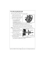
OPERATION

NOTE:

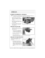
Check that there is a 1.5 mm clearance between the tool rests and the 

surface of the grinding wheel. Adjust as necessary. Re-check the gap 

between the spark deflectors and the surface of the grinding wheels. 

These should also be a maximum of 2 mm. Adjust as necessary.

NOTE:

Check that the eyeshields have been secured in the correct position 

and that the grinding wheel lock nuts are tight.

1. Stand to the side of the bench grinder and switch it on using the on/off 

switch.
• Let the grinding wheel reach full speed before grinding. 
• The wheel rotates in the same direction as the arrow stamped in the 

side of the wheel guard.

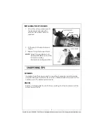
2. Hold the work piece firmly against the tool rest. Hold very small pieces with 

pliers or other suitable clamps. 

3. Feed the work piece smoothly and evenly against the grinding wheel. 
4. When grinding, always keep the work piece moving across the face of the 

wheel. Grinding against the same part of the wheel will cause uneven 

wear of the wheel face.

5. Grind only on the face of the grinding wheel and never the side of it. 

(Some wheels are designed for side grinding and will say so on their 

packaging.)

NOTE:

Prolonged grinding will cause most tools to become hot. Use care 

when handling hot tools. 

6. Switch the bench grinder off using the on/off switch when you have 

finished.

USING THE BUILT IN LIGHT

The built in light will come on automatically whenever the bench grinder is 

switched on.
The arm can bend to set the light in a suitable position.

CAUTION: KEEP ALL BYSTANDERS A SAFE DISTANCE AWAY FROM THE 

TOOL AND NOT IN DIRECT LINE, FRONT OR BACK OF THE GRINDER. 

CAUTION: ALWAYS WEAR SAFETY GLASSES 

Summary of Contents for Metalworker CBG6250L

Page 1: ...OPERATION MAINTENANCE INSTRUCTIONS LS0811 BENCH GRINDER WITH LIGHT AND WHEEL DRESSER MODEL NO CBG6250L PART NO 6500524...

Page 2: ...nths from the date of purchase Please keep your receipt which will be required as proof of purchase This guarantee is invalid if the product is found to have been abused or tampered with in any way or...

Page 3: ...for outdoor use Use of a cable suitable for outdoor use reduces the risk of electric shock 5 If operating the power tool in a damp location is unavoidable use a residual current device RCD protected...

Page 4: ...orking conditions and the work to be performed Use of the power tool for operations different from intended could result in a hazardous situation 7 The performance of this tool may vary depending upon...

Page 5: ...ire or serious injury 9 Gloves manufactured to the current European safety standards should be worn when operating grinding equipment 10 Eye protection manufactured to the current European safety stan...

Page 6: ...zard If the colours of the wires in the power cable of this product do not correspond with the markings on the terminals of your plug proceed as follows The wire which is coloured Blue must be connect...

Page 7: ...Clarke dealer where you purchased the bench grinder PART IDENTIFICATION 1 x Bench Grinder Assembly 2 grinding wheels attached 2 x Eye Shields 1 with Built in Magnifying Lens 2 x Eye Shield Arms with...

Page 8: ...mount the bench grinder on a vibration absorbing mat INSTALLING THE TOOL RESTS 1 Fix the tool rests to the bench grinder with the screw and hand knob as shown The tool rests are adjustable and should...

Page 9: ...shown 3 Repeat for right side eye shield NOTE Adjust the eye shields to an appropriate distance from the tool rests avoiding interference during operation SHARPENING TIPS SCISSORS If possible take the...

Page 10: ...ly against the tool rest Hold very small pieces with pliers or other suitable clamps 3 Feed the work piece smoothly and evenly against the grinding wheel 4 When grinding always keep the work piece mov...

Page 11: ...asive wheels start to become clogged with debris use the dresser tool supplied to clean dress them 1 Start the bench grinder running 2 Place the dresser tool on the tool rest with the dresser wheels f...

Page 12: ...r than the speed marked on the nameplate of the tool and have maximum dimensions of 150 mm diameter 20 mm thick with a bore size of 12 7 mm Inspect the wheel for cracks chips or any other visible dama...

Page 13: ...13 Parts Service 020 8988 7400 E mail Parts clarkeinternational com or Service clarkeinternational com PARTS DIAGRAM...

Page 14: ...shield WACBG6250L30 31 Work Rest Lock knob WACBG6250L31 32 Standard Washer WACBG6250L32 33 Flat Washer WACBG6250L33 34 I type Hex Nut WACBG6250L34 35 Nut WACBG6250L35 36 Wheel 60 WACBG6250L36 37 Locke...

Page 15: ...15 Parts Service 020 8988 7400 E mail Parts clarkeinternational com or Service clarkeinternational com DECLARATION OF CONFORMITY...

Page 16: ......

Reviews: