12
Parts & Service: 020 8988 7400 / E-mail: Parts@clarkeinternational.com or Service@clarkeinternational.com
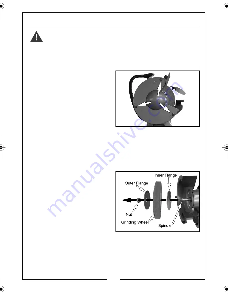
REPLACING THE WHEELS
1. Loosen the screws shown and
rotate and remove the cover.
2. Hold the other wheel by hand, and
remove the nut and outer flange.
NOTE:
The left hand wheel locking
nut has a left handed thread.
3. Slide off the old wheel and replace
with a new one.
• Use only wheels recommended
by the manufacturer which have a marked speed equal to or
greater than the speed marked on the nameplate of the tool
• The disc should have maximum dimensions of 150 mm diameter, 20
mm thick with a bore size of 12.7 mm.
• Inspect the wheel for cracks, chips or any other visible damage,
damaged abrasive products must be destroyed and discarded
4. Replace the outer flange.
• Make sure both wheel flanges
are placed with the concave
sides towards the wheel.
5. Replace the nut securely.
• Do not overtighten as this may
damage the grinding wheel.
6. Re-assemble the guards fully prior
to carrying out testing.
• Each time after mounting, the wheel should be test run for a
reasonable time (approximately 1 minute).
WARNING: THE POSITIONS OF THE GRINDING WHEEL AND WIRE WHEEL
SHOULD NOT
BE INTERCHANGED, AS THIS MAY RESULT IN INJURY OR
DAMAGE TO THE PRODUCT
WARNING: DO NOT USE DAMAGED GRINDING WHEELS.
WARNING: SWITCH THE GRINDER OFF AND DISCONNECT THE POWER
SUPPLY BEFORE CHANGING THE GRINDING WHEELS
CBG6250LW Bench Grinder.fm Page 12 Thursday, November 10, 2011 2:59 PM
Summary of Contents for Metalworker CBG6250LW
Page 16: ......


