18
C. BEVEL CUTTING
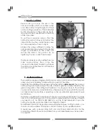
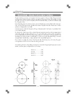
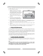
Bevel cutting involves the use of the
compound slide, which is mounted on the
cross-slide and set at right angles to it for all
normal cutting operations. This is indicated
by the zero mark, on the scale, (B, Fig. 8),
lining up with the mark etched on the body
of the cross-slide.
To set the compound slide so that the
cutting tool will cut a bevel, first retract the
slide, until the two hex. socket head screws
(A), are revealed as shown in Fig 8.
Slacken the screws sufficient to allow the
compound slide to be turned to the desired
angle, as indicated on the scale, and
secure the slide in this position by re-
tightening the hex. socket head screws.
The taper, or bevel, is cut by setting the cross
slide appropriately then using the
compound slide feed handle to advance
the cutting tool in the direction of the arrow
as shown in Fig.9.
D. SCREWCUTTING
This operation requires a degree of skill and accuracy, and should not be attempted
unless you are completely familiar with all aspects of the lathe.
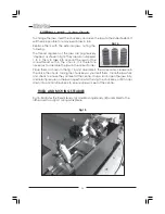
Essentially, the saddle will move towards the headstock
under power,
the same as
cutting using auto feed, except the rate of feed is greater, as determined by the
gear configuration. The cutting tool therefore, is moving ever closer to the rotating
chuck. Great care and concentration must be exercised to ensure that the two do
not meet when the machine is operating, as the possible damage caused could
be disastrous.
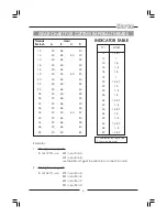
The lathe is supplied with a leadscrew that will produce Imperial Threads in a range
from 12 to 104 threads per inch. It is important to remember that the type of thread
you need to cut, i.e. UNF, BA, BSP, BSW etc., will be totally dependant upon the
cutting tool profile, as profiles differ from thread to thread.
For detailed information regarding screwcutting techniques, cutting tools etc., you
should consult a suitable handbook or obtain advice from a qualified person.
A leadscrew, with corresponding half nuts and thread dial indicator, for the
production of Metric threads is available from your Clarke dealer, see ‘Accessories’
on page 24.
Fig 9
Fig 8
Summary of Contents for MetalWorker CL300M
Page 1: ...1 OPERATING MAINTENANCE INSTRUCTIONS 300mm VARIABLE SPEED METAL LATHE Model No CL300M 1008...
Page 4: ...4...
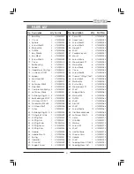
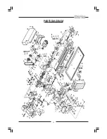
Page 29: ...29 PARTS DIAGRAM...
Page 30: ...30 WIRING DIAGRAM...
Page 31: ...31 NOTES...
Page 32: ...32...


