20
CHANGING GEARS FOR SCREWCUTTING
The leadscrew is driven, via a gear train, by a gear on the spindle. The gear ratio
will therefore determine the rotational speed of the leadscrew with relation to the
spindle. i.e. one turn of the spindle will turn the leadscrew an amount determined
by the gear ratio.
By setting the gears to a known ratio, we can therefore produce threads to a known
size, and as the leadscrew supplied produces Imperial threads, the known values
will be in Threads Per Inch (TPI).
A leadscrew for Metric thread cutting, complete with half nuts is available from
your Clarke dealer.
As previously mentioned, the actual thread produced will be totally dependant
upon the profile of the cutting tool. It is not within the scope of this manual to
provide detailed information regarding types of cutting tool, cutting speeds and
working with various types of material etc., and it is strongly advised that you consult
appropriate handbooks or seek advice from a qualified person.
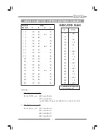
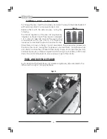
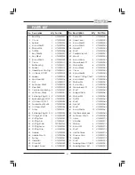
The chart, on page 20, shows the thread sizes that may be cut using the gear
configuration shown in the corresponding columns.
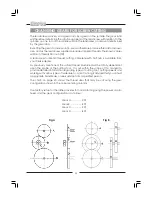
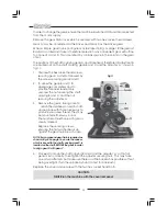
The factory setup for the lathe provides for normal turning using the power or auto
feed, and the gear configuration is as follows:
Gear A ................. 20T
Gear B .................. 80T
Gear C ................. 20T
Gear D ................. 80T
Fig A
Fig B
Summary of Contents for MetalWorker CL300M
Page 1: ...1 OPERATING MAINTENANCE INSTRUCTIONS 300mm VARIABLE SPEED METAL LATHE Model No CL300M 1008...
Page 4: ...4...
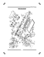
Page 29: ...29 PARTS DIAGRAM...
Page 30: ...30 WIRING DIAGRAM...
Page 31: ...31 NOTES...
Page 32: ...32...


