-9-
-10-
Installation and Assembly
(Figures in brackets refer to parts diag page 13)
IMPORTANT:
Careful
consideration is required when
choosing the location for the
machine, special attention should
be paid to the operation, i.e. the
X & Y-axis, powerpoint etc, also
the workbench where the
machine is to be installed should
be firm flat and level. Avoid
installing in direct sunshine, damp
or very dusty location.
1.
Choose suitable location,
taking into consideration
the operation, i.e. the X & Y-
axis,allow sufficient clearance
Wall
Wall
15cm min
25cm
min
105cm
210cm
3 x Ø 8.5mm
especially on the right hand side of the machine to enable unhindered use of the
handwheel etc.
2.
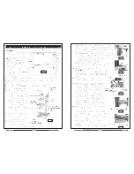
Drill three 8.5mm in workbench where machine is to be installed, (see Fig.1).
NOTE; before drilling, observe the min distances from the walls, anything less could impair
the maximum use of the machine.
3.
Using suitable 8mm dia bolts, (not supplied), bolt machine firmly in position.
4.
Fit three handles, (97,98,99), to handwheels, (see Fig. 2 A).
Fig. 1
A
5.
Fit handle, (87), (see Fig.2 B).
6.
Your machine has been
coated with rust protection to
protect it in shipping, all traces
of this must be removed before
attempting to use the machine.
Commercial degreaser,
kerosene or similar solvent may
be used to remove this
protection, care must be taken
to avoid getting solvent into
the motor and electrical parts
i.e. switches etc, also observe
the cleaner manufactures
instructions.
7.
After cleaning, lightly coat all
bright (non painted) surfaces,
with a light machine oil, lightly
lubricate all moving parts, i.e.
handwheel threads etc.
8.
Remove drill chuck/taper
shank if fitted, to do this, pull
out the protective cover on
B
DC Motor
Lift Handwheel
A
Longitudal feed
Handwheel
Y
Axis
Cross Feed
Handwheel
X
Axis
Guard
Protective Cover
Fine Feed
Handwheel
the top of the mill head (see Fig. 2), insert the tommy bar into the hole in the spindle
Fig. 2
(see Fig. 3), whilst holding spindle with tommy bar, loosen
the spindle draw bar using 8mm spanner (see Fig. 4).
Remove tommy bar, and store safely. Unscrew the draw
bar approx three full turns, whilst supporting the drill chuck
with one hand, gently, using a plastic mallet or similar, DO
NOT USE HAMMER, apply a swift blow to the top of the draw
bar,this should cause the chuck to fall, if not repeat with
plastic hammer applying a little more force. Once the
chuck is free, continue to support with one hand and
unscrew the draw bar completely until the chuck can be
removed, store removed parts safely.
NOTE: If removing taper shank with cutting tool inserted, use
protection such as industrial work gloves or a wad of cloth
etc to protect your hands.
9. Your Machine is now ready for testing.
IMPORTANT: before plugging in and switching ON,
ensure all items such as chuck keys tommy bars etc
are removed. Set the machine HIGH/LOW range
knob (see Fig. 5), to LOW, Set forward reverse switch to
forward.
Fig. 3
10. Plug machine into main electrical supply
and switch ON, ensuring the correct supply is
available.
11. Switch the machine on by turning the speed
control knob slowly clockwise. A click will be
heard as the power is turned ON, continue
to slowly turn the Knob until the spindle starts
turning, run the machine at a slow speed for
5 minutes, at the end of that period,
providing there are no apparent problems
i.e. adverse noises etc, rotate the speed
control knob slowly clockwise until maximum
speed is reached, continue to run at this
speed for a further 2 minutes. when 2 minutes
has elapsed, slowly turn the speed control
Power ON LED
Fuse
Forward, OFF,
Reverse Switch
Speed Control Knob
High/Low
Knob
knob anticlockwise until a click is heard and the
power is turned OFF, turn forward, reverse switch to
the centre position OFF.
12. Before using the machine for the first time, test all
functions: refer to Fig.2.
a. Test vertical travel of the milling head by turning the
lift handwheel in both directions, apply the vertical
lock, (see Fig. 6), attempt to turn the lift handwheel,
head should not move, DO NOT FORCE.
b. Test longitudal travel of the bed by turning the
longitudal handwheel in both directions.
c.
Test cross feed travel by turning cross feed
handwheel in both directions.
NOTE: Both longitudal and cross travel can be
locked, with respective allen screws, (see Fig. 7)
Tommy Bar
Vertical Lock Clutch Lever
Fig. 4
Fig. 6
Fig. 5
Fig. 7
Longitudal Lock
Cross Lock
156cm
A
Summary of Contents for Metalworker CMD10
Page 2: ... 1 18 NOTES ...


