4
WATER CONNECTIONS
IMPORTANT
:
DO NOT connect the pump to the power supply until the hose/pipe
installation is completed.
Because of the variety of possible installations, no plumbing accessories are
supplied as standard with your pump. However, accessories designed specifically
for this range of pumps are available from your CLARKE dealer and are listed on
page 6.
from an above ground pool. However, it is possible
to draw water from a sunken pool, providing the
suction lift does not exceed the distance specified
for your pump (see Specifications on page 7).
A. SUCTION LIFT
The suction lift i.e. the vertical distance between
the water level and the pump should not exceed
the distance specified for your pump (see
Specifications on page 7).
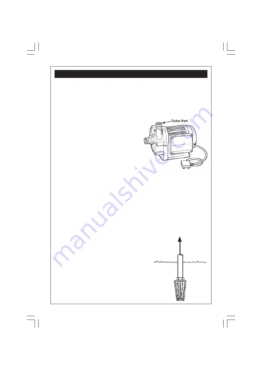
A foot valve/filter MUST be fitted to the lower end
of the suction hose, (as illustrated in fig.2), so as to
help retain water in the suction system.
Remember.... this is NOT a self priming pump.
The pump must always be installed and
operated in a horizontal position i.e. with the
outlet port (see Fig.1), facing vertically
upwards. The fixing slots in the base should
be used as necessary to secure the pump
firmly in its operating position. Also, ensure
that there is adequate air circulation around
the motor.
Avoid situations where there is the risk of
water coming into contact with the outside
of the pump. Neither the motor or the
terminal box are intended to be waterproof.
Attach suitable 1” ID hose to the inlet port, securing with a worm drive clip. The
other end of the hose should be connected to a strainer, or foot valve/filter
depending upon the type of installation (see below), and should rest on the bottom
of the pool. Ensure all connections are air tight.
Attach also a suitable 1” ID hose to the outlet port using a worm drive clip. The
other end of the hose should be connected to your Water Filter (available from
your Clarke dealer - see page 6). Ensure there are no kinks in the hose.
These notes are for guidance on how to achieve a proper working system.
The schematic diagrams, figs. 3 and 4, illustrate possible methods of pipework
installation. This pump is designed primarily, to br gravity fed, that is, drawing water
Fig.1
Foot Valve/
Filter
Fig.2


