background image

5

The delivery head i.e. the vertical
distance between the pump and
the point of discharge should not
exceed distance specified for your
pump (see Specifications,  page
7).

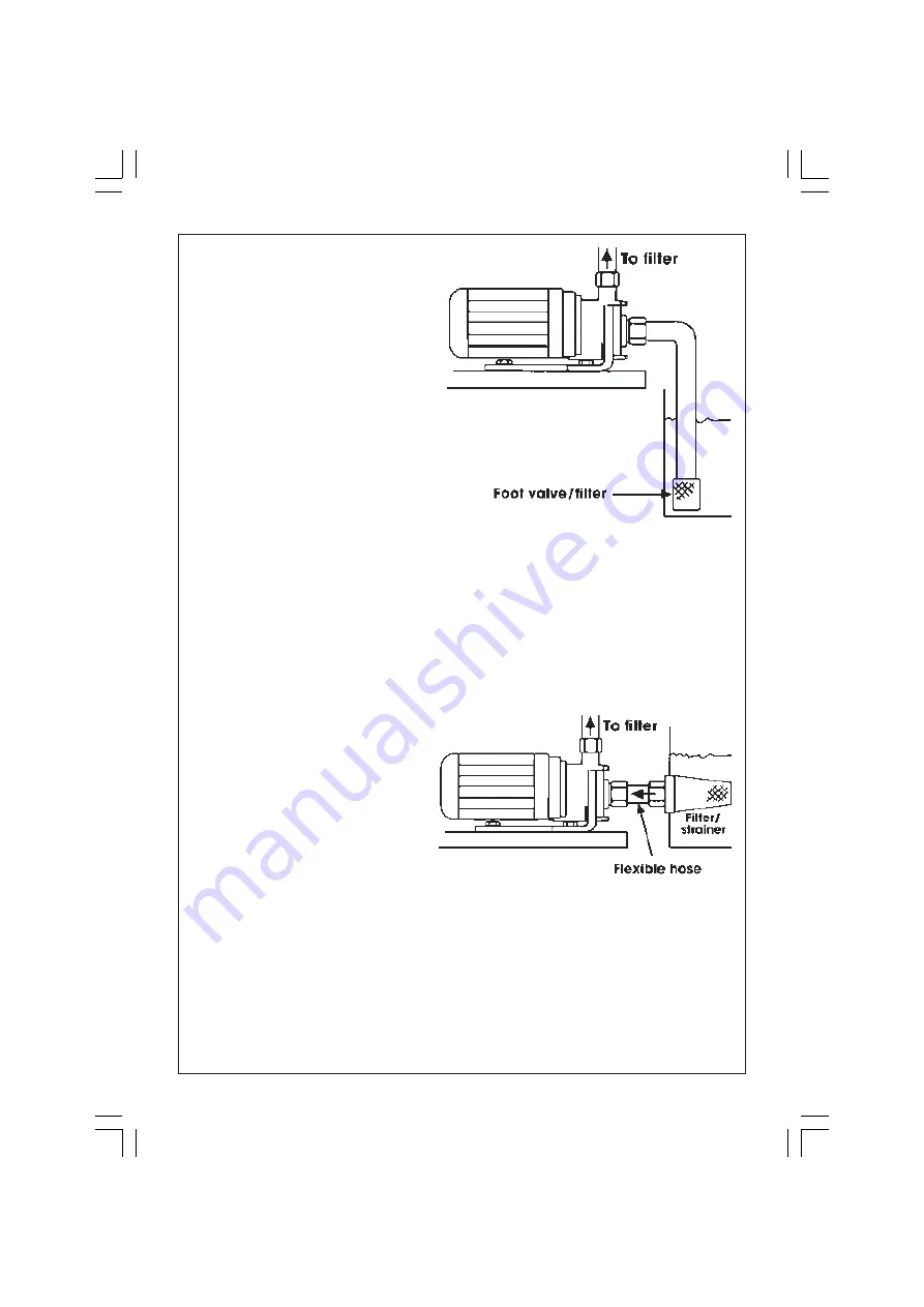
When suction lift is used to draw
water into the pump it is essential
that all connections and hoses are

1.

With the pump, all inlet pipes/hoses and the foot valve in position, slowly pour
water into the outlet port. Wait until all air is expelled...this may take a minute
or two...and fill to the brim before connecting the outlet hose to the outlet
port.  The hose is then led away to the water filter.

2.

Switch on the pump. Water should start to flow through the system.

Check for leaks and repair as necessary

Do not allow the pump to run dry, otherwise the seal between the pump and motor
may be damaged. If a leak is noticed at this point it may indicate that the seal is
worn and therefore in need of replacement. Contact your CLARKE dealer, or the
Clarke International Service Department for advice.

B

GRAVITY FEED

Do not place any restriction on the
inlet side of the pump.

The delivery head i.e. the vertical
distance between the pump outlet
and the point of discharge should
not exceed distance specified for
your pump (see Specifications,  page 7).

To prevent unnecessary strain or possible distortion to the pump, ensure that
adequate support is provided to the hoses and/or pipes. Remember they will be
considerably heavier when filled with water.

Remember - this pump is designed for pumping CLEAN WATER with small solids in
suspension, ONLY. DO NOT USE for pumping chemicals or other corrosive liquids
(other than pool purification chemicals in their correct mix ratio).

Protect the pump and pipework from 

freezing. 

The formation of ice may cause

serious damage.

NOTE: For the fitting of filters/strainers, please consult the manufacturers manual.

completely air tight, otherwise the system will
not work.

Before pumping will start it is essential to
completely fill the suction side with water. This
is known as 

priming the pump

 and is carried

out as follows :-

Fig.4

Fig.3

Summary of Contents for SPP3

Page 1: ...OPERATING MAINTENANCE INSTRUCTIONS POND PUMP Model Nos SPP3 SPP6 0200 ...

Page 2: ... effect your statutory rights SAFETY PRECAUTIONS 1 Ensure the pump is installed in a horizontal position with the outlet facing vertically upwards and that it is firmly anchored via its fixing screws 2 Ensure there is an adequate air flow around the pump DO NOT mount it in an enclosed atmosphere 3 Ensure all water pipes supply or discharge are adequately supported where necessary so as not to put ...

Page 3: ...l marked with N or coloured BLACK If this appliance is fitted with a plug which is moulded onto the electric cable i e non rewirable please note 1 The plug must be thrown away if it is cut from the electric cable There is a danger of electric shock if it is subsequently inserted into a socket outlet 2 Never use the plug without the fuse cover fitted 3 Should you wish to replace a detachable fuse c...

Page 4: ...sition i e with the outlet port see Fig 1 facing vertically upwards The fixing slots in the base should be used as necessary to secure the pump firmly in its operating position Also ensure that there is adequate air circulation around the motor Avoid situations where there is the risk of water coming into contact with the outside of the pump Neither the motor or the terminal box are intended to be...

Page 5: ... Clarke International Service Department for advice B GRAVITY FEED Do not place any restriction on the inlet side of the pump The delivery head i e the vertical distance between the pump outlet and the point of discharge should not exceed distance specified for your pump see Specifications page 7 To prevent unnecessary strain or possible distortion to the pump ensure that adequate support is provi...

Page 6: ... 2 Check to see that no foreign matter is fouling the intake system check the strainer is not blocked or obstructed Should you still experience problems then contact your Clarke dealer or CLARKE International Service Department for advice Please contact your nearest dealer or CLARKE International on one of the following numbers PARTS SERVICE TEL 020 8988 7400 PARTS SERVICE FAX 020 8558 3622 or e m...

Page 7: ... Max Output 60 L min 3 6M3 h 100 L min 6M3 h Insulation Rating IP44 IP44 Dimensions LxWxH 255x150x190mm 255x150x190mm Part No 7175010 7175020 NOTE As the pumping head is increased so the flow rate of water will decrease Please note that the details and specifications contained herein are correct at the time of going to print However CLARKE International reserve the right to change specifications a...

Page 8: ...PARTS DIAGRAM 8 ...

Page 9: ...P1240012 6 Sealing ring LDP1200027 7 Gasket LDS3500199 8 Terminal box LDS3500214 9 Capacitor LDP1360009 10 Screw LDP1100004 11 Seal LDP1200021 12 Screw LDP1100006 13 Cover LDP3500218 14 Screw LDP1100006 15 Washer LDP1120003 16 Cable clamp LDP1510004 17 Switch assembly LDP1380001 18 Power Cable LDP1330013 19 Nut LDP1510009 20 Cable Gland LDP1230001 21 Motor Assembly n a 9 ...

Reviews: