5
Parts & Service: 020 8988 7400 / E-mail: Parts@clarkeinternational.com or Service@clarkeinternational.com
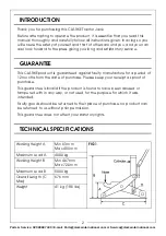
mounting, sufficient to allow the ram to be located at ‘D’, Fig. 1. The
securing bolt may then be tightened.
2. Stand the jack upright and fit the handle as follows:
3. Unscrew the bolt, on the side of the jack handle housing, sufficient for the
grooved end of the handle to be inserted fully, and for the drive, in the end
of the handle, to engage with the tapered square end of the valve
operating connecting rod.
4. Retighten the bolt fully to secure the handle.
5. Attach the handle extension and secure with the bolt provided.
TO RAISE A LOAD
1. Ensure the load is chocked and stable, and on firm level ground, before
manoeuvring the jack so that the groove in the nose or the top of the
cylinder, whichever is to be used, is directly beneath the lifting point.
2. Turn the handle fully clockwise, then pump the handle to raise the jack, so
that contact is made with the lifting point.
3. Make one final check to ensure that there are no obstacles to the lift, and
that all personnel are well clear before continuing to pump the handle and
lift the load.
4. NEVER allow any individual to get beneath the load until it is firmly chocked
or supported on axle stands or similar supports.
TO LOWER THE LOAD
1. With the axle stands/supports removed, check to ensure that there are no
personnel in the immediate vicinity before VERY SLOWLY turning the lifting
handle anticlockwise and allowing the jack to lower the load.
WARNING: BEFORE LIFTING, ENSURE THE SAFETY PRECAUTIONS ARE
STRICTLY FOLLOWED. NO RESPONSIBILITY CAN BE ACCEPTED FOR
INCORRECT USE OF THE JACK
WARNING: PLEASE NOTE THAT THE SCISSOR ACTION OF THE JACK WILL
CAUSE THE JACK TO MOVE SLIGHTLY AS IT IS RAISED AND LOWERED. IT IS
MOST IMPORTANT THAT THIS MOVEMENT IS NOT RESTRICTED IN ANY WAY.
ENSURE THE GROUND IN THE IMMEDIATE VICINITY OF THE JACK IS FREE
FROM DEBRIS.


