background image

6

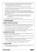
2. Return the jack to upright and refill with hydraulic oil up to the lower rim of 

the filler hole.

3. Purge any air from the system and replace the filler plug.

4. Dispose of old oil appropriately and be sure to wipe up any spillage.

GENERAL CARE

1. Periodically lubricate the hinges, front wheels & rear castors with light oil.

2. Store in a dry location with the arm in its lowest position.

3. In the event of damage or broken components, replacements are 

available from Clarke Parts & Service.

TROUBLESHOOTING

If any of these remedies fail to restore your jack, consult your Clarke dealer.

PROBLEM

CAUSE

SOLUTION

Jack will not lift 
the rated load

Low oil level

See ‘Checking the Oil Level‘

Release valve not 
closed

Turn the release knob fully clockwise

Air in the hydraulic 
system

Purge the system as on page 5

Jack lower when 
under load

Release valve not 
fully closed

Turn the release knob fully clockwise

Air in the hydraulic 
system

Purge the system as on page 5

Pump feels 
Spongy

Low oil level

See ‘Checking the Oil Level‘

Air in the hydraulic 
system

Purge the system as on page 5

Handle raises or 
flies back under 
load

Air in the hydraulic 
system

Purge the system as on page 5

Jack will not lift 
full height

Low oil level

See ‘Checking the Oil Level‘

Air in the system

Purge the system as on page 5

Jack will not 
lower completely

Return spring may 
be faulty

Return to  your Clarke dealer for 
repair

Summary of Contents for Strong-Arm CTJ2250LP

Page 1: ...OPERATION MAINTENANCE INSTRUCTIONS ORIGINAL INSTRUCTIONS GC0719 ISS 2 2 TONNE TROLLEY JACK MODEL NO CTJ2250LP PART NO 7623070...

Page 2: ...se keep your receipt which will be required as proof of purchase This guarantee is invalid if the product is found to have been abused or tampered with in any way or not used for it s intended purpose...

Page 3: ...product If working under a vehicle always use axle stands designed for the purpose 7 Ensure the jack is on a firm solid base and that there is no likelihood of it slipping when under load 8 Ensure th...

Page 4: ...n Fig 1and turn it clockwise to close the valve 4 Insert the handle into the handle sleeve and pump the handle to raise the saddle until it reaches the vehicle lifting point NOTE The control valve is...

Page 5: ...bbles become trapped inside the hydraulic system the efficiency of the jack will be reduced Any air can be purged from the system as follows 1 Turn the control valve counter clockwise and remove the f...

Page 6: ...OLUTION Jack will not lift the rated load Low oil level See Checking the Oil Level Release valve not closed Turn the release knob fully clockwise Air in the hydraulic system Purge the system as on pag...

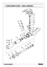
Page 7: ...7 COMPONENT PARTS RAM ASSEMBLY...

Page 8: ...39 Back up ring 12 Rear castor assembly 40 U seal 13 Spring washer 41 Pump cylinder 14 Nut M8 42 Pump body 15 Carrying handle 43 Swivel 16 Cover 44 Steel ball 17 Bolt M5 x 15 45 Release valve 18 Retai...

Page 9: ...9 COMPONENT PARTS GENERAL ASSEMBLY...

Page 10: ...Guide ring 71 Pump connecting clip 63 Ram piston 72 Actuating piston 64 Nylon washer Hydraulic seal kit 65 Reservoir end cap ENVIRONMENTAL PROTECTION One of the most damaging sources of environmental...

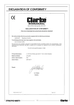
Page 11: ...11 DECLARATION OF CONFORMITY...

Page 12: ......

Reviews: