background image

No.

Description

Part No.

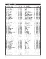
PARTS LIST

No.

Description

Part No.

17

 1

Circlip For Shaft

 1

GRCMS1001

 2

Pressure Rod

 1

GRCMS1002

 3

Screw  M4×55

 2

GRCMS1003

 4

Spring Lock Washer

 2

GRCMS1004

 5

Screw  M4×10

 4

GRCMS1005

 6

Cable Clip

 2

GRCMS1006

 7

Shaft

 1

GRCMS1007

 8

Split Washer

 1

GRCMS1008

 8-1

Screw  M4.2×9

 1

GRCMS1008-1

 9

Split Washer

 1

GRCMS1009

 10

Cable Plug

 1

GRCMS1010

 11

Extension Spring

 1

GRCMS1011

 12

Push Rod

 1

GRCMS1012

 13

Head

 1

GRCMS1013

 14

Plain Washer

 9

GRCMS1014

 15

Spring Lock Washer

 9

GRCMS1015

 16

Screw M4×30

 4

GRCMS1016

 17

O-Ring

 1

GRCMS1017

 18

Stop Lever

 1

GRCMS1018

 19

Plain Washe

 1

GRCMS1019

 20

Nut M12

 1

GRCMS1020

 21

Nut M5

 4

GRCMS1021

22

Handle (Upper)

 1

GRCMS1022

23

Capacitor

 1

GRCMS1023

24

Switch

 1

GRCMS1024

25

Inductor

 1

GRCMS1025

26

Handle (Upper Down)

 1

GRCMS1026

27

Screw M4×22

 3

GRCMS1027

28

Cover

 1

GRCMS1028

29

Bolt M8×15(left)

 1

GRCMS1029

30

Wheel Flange

 1

GRCMS1030

31

Below Wheel Flange

 1

GRCMS1031

32

Wheel Flange Washer

 1

GRCMS1032

33

Screw M4×8

 3

GRCMS1033

34

Bearing Cover plate

 1

GRCMS1034

35

Protective Cover

 1

GRCMS1035

36

Bearing D180201

 1

GRCMS1036

37

Fore Cover

 1

GRCMS1037

38

Output Spindle

 1

GRCMS1038

39

Woodruff Key

 1

GRCMS1039

40

Screw M5×10

 1

GRCMS1040

41

Bevel Gear

 1

GRCMS1041

42

Axle Elasticity Ring 12

 1

GRCMS1042

43

Oil Bearing

 1

GRCMS1043

44

Cable Base

 1

GRCMS1044

45

Screw

 1

GRCMS1045

46

Cable

 1

GRCMS1046

47

Cable Armor

 1

GRCMS1047

48

Rubber Washer

2

GRCMS1048

49

Cable Armor

 1

GRCMS1049

50

Nut Wrench

 1

GRCMS1050

51

Lengthening Nut

 1

GRCMS1051

52

Armor

 1

GRCMS1052

53

Spring

 2

GRCMS1053

54

Frame

 1

GRCMS1054

55

Copper Washer

 1

GRCMS1055

56

Spring Lock Washer

 4

GRCMS1056

57

Screw M5×8

 4

GRCMS1057

58

Blade Protective Plate

 2

GRCMS1058

59

Socket Hd Cap Screw

 4

GRCMS1059

60

Bolt M8×70

 2

GRCMS1060

61

Turntable Locking Screw

 3

GRCMS1061

62

Socket Hd Cap Screw

 2

GRCMS1062

62-1 Socket Hd Cap Screw

GRCMS1062-1

63

Washer

 2

GRCMS1063

64

Nut M8

 1

GRCMS1064

65

Nut M12

 2

GRCMS1065

66

Frame Rotation

 2

GRCMS1066

67

Spring Fixed Seat

 1

GRCMS1067

68

Washer

 1

GRCMS1068

69

Blade Carrier Rotation

 1

GRCMS1069

70

Base

 1

GRCMS1070

71

 Screw M5×12

 2

GRCMS1071

72

Fence

 1

GRCMS1072

73

Turntable

 1

GRCMS1073

74

Nut M6

 4

GRCMS1074

75

Plain Washer 6

 2

GRCMS1075

  76

Base Table

 1

GRCMS1076

77

Right-angle Piece

 2

GRCMS1077

78

Basetable Washer

 6

GRCMS1078

79

Screw M4×65

 2

GRCMS1079

80

Brush Holder

 2

GRCMS1080

81

Carbon Brush

 2

GRCMS1081

82

Screw

 4

GRCMS1082

83

Bearing D18201

 1

GRCMS1083

84

Armature

 1

GRCMS1084

85

Bearing 80029

 1

GRCMS1085

86

Fan Guide

 1

GRCMS1086

87

Stator

 1

GRCMS1087

88

Bushing

 1

GRCMS1088

89

Housing

 1

GRCMS1089

90

Rear Cover

 1

GRCMS1090

91

Wrench

 1

GRCMS1091

92

Wrench Socket

 1

GRCMS1092

93

Screw M4x16

 2

GRCMS1093

94

Nut

 2

GRCMS1094

95

Connection Box

1

GRCMS1095

96

Connection Box Cover

1

GRCMS1096

97

Screw

2

GRCMS1097

98

Connection Terminal

 1

GRCMS1098

99

Cable Clip

 1

GRCMS1099

Summary of Contents for woodworker CMS10 6501305

Page 1: ...02 08 Part Number 6501305 Operating Maintenance Instructions 10 COMPOUND MITRE SAW 10 COMPOUND MITRE SAW Model CMS10...

Page 2: ...pindle Diameter 16 mm Dust Port Diameter 31 37 mm Inner Outer Sound Power level measured 99 3 dBLWA Vibration Level 2 5 m s Normal Load Net weight 11 5 kg Part Number 6501305 Please note that the deta...

Page 3: ...ase keep your receipt as proof of purchase This guarantee is invalid if the product is found to have been abused or tampered with in any way or not used for the purpose for which it was intended Fault...

Page 4: ...DAMAGE Before using the machine any damaged part such as a guard etc should be checked to ensure that it will operate properly and perform its intended function Check for alignment of moving parts br...

Page 5: ...N MACHINE IN TOP CONDITION Keep tools sharp and clean for the best and safest performance Follow maintenance instructions 21 DON T OVERREACH Keep your proper footing and balance at all times For best...

Page 6: ...st all be in place and securely fastened when performing any operation 10 Use ONLY approved replacement saw blades Contact your local CLARKE dealer for advice The use of inferior blades may increase t...

Page 7: ...d with a plug which is moulded onto the electric cable i e non rewirable please note 1 The plug must be thrown away if it is cut from the electric cable There is a danger of electric shock if it is su...

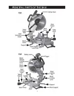
Page 8: ...PRINCIPAL PARTS OF THE SAW 8 Fig 1 Fig 2...

Page 9: ...ations on page 3 A dust extraction outlet is provided at the rear of the machine on to which the dust bag supplied is fitted If necessary hose from a vacuum cleaner may be attached to provide fast and...

Page 10: ...ted to a workbench the rear support must be fitted see Figs 1 and 2 A single bolt secures the support to the rear of the base housing The Cutting Head is locked in its lower position for transit purpo...

Page 11: ...treat the machine with indifference and NEVER be casual with your approach To switch off release the trigger whilst still maintaining full control of the head NEVER allow the head to spring upwards a...

Page 12: ...g lever and swing the head to the side Lower the arm and bring your template up to the saw blade When satisfied that the edge of template and blade are parallel lock the head in position with locking...

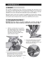
Page 13: ...ARKE dealer for advice 2 Changing the Saw Blade IMPORTANT Exercise extreme care when handling the saw blade The tips are extremely sharp and careless handling could result in severe personal injury 13...

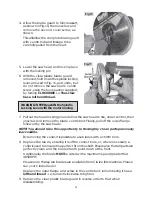
Page 14: ...e outer flange followed by the saw blade NOTE You should take this opportunity to thoroughly clean parts previously inaccessible By removing the collar it is possible to use blades with a 16mm bore 8...

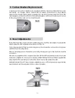
Page 15: ...just the head using the 90 adjuster screw shown in Fig 13 To do this slacken off the bevel locking lever then lower the arm and lock in place with the head locking knob Place a small square on the tab...

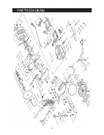
Page 16: ...PARTS DIAGRAM 16...

Page 17: ...1 GRCMS1045 46 Cable 1 GRCMS1046 47 Cable Armor 1 GRCMS1047 48 Rubber Washer 2 GRCMS1048 49 Cable Armor 1 GRCMS1049 50 Nut Wrench 1 GRCMS1050 51 Lengthening Nut 1 GRCMS1051 52 Armor 1 GRCMS1052 53 Sp...

Page 18: ...18...

Page 19: ...19...

Page 20: ......

Reviews: