ELECTRICAL CONNECTIONS
7
WARNING! THIS APPLIANCE MUST BE EARTHED
IMPORTANT:
Connect the mains lead to a standard, 230 Volt (50Hz) electrical
supply through an approved 13 amp BS 1363 plug, or a suitably fused isolator
switch. The wires in the mains lead are coloured in accordance with the following
code:
Green & Yellow
-
Earth
Blue
-
Neutral
Brown
-
Live
As the colours of the flexible cord of this appliance may not correspond with the
coloured markings identifying terminals in your plug proceed as follows:
•
Connect GREEN & YELLOW cord to terminal marked with a letter “E” or
Earth symbol “ ” or coloured GREEN or GREEN & YELLOW.
•
Connect BROWN cord to terminal marked with a letter “L” or coloured RED
•
Connect BLUE cord to terminal marked with a letter “N” or coloured BLACK
We recommend that this machine is connected to the mains supply through a
Residual Current Device.
In the event that this appliance is fitted with a plug which is moulded onto the
electric cable (i.e. non-rewirable) please note:
1.
The plug must be thrown away if it is cut from the electric cable. There is a
danger of electric shock if it is subsequently inserted into a socket outlet.
2.
Never use the plug without the fuse cover fitted.
3.
Should you wish to replace a detachable fuse carrier, ensure that the correct
replacement is used (as indicated by marking or colour code).
4.
Replacement fuse covers can be obtained from your local dealer or most
electrical stockists.
5.
The fuse in the plug must be replaced with one of the same rating
(13 amps
)
and this replacement must be approved to BS1362.
If in doubt, consult a qualified electrician. Do not attempt any electrical repairs
yourself.
STARTING PROCEDURE.
1.
Having prepared the lathe in accordance with the instructions given, ensure
the work is properly centralised, properly held, and is completely secure. Turn
the workpiece by hand to ensure that it moves freely without interference.
2.
Remove any wood shavings, and ensure that no loose tools are in the vicinity.
3.
Check ALL clamps securing the Headstock, Tool Rest and Tailstock, to ensure
they are firmly clamped.
4.
Switch on the machine
ensuring it is set to its slowest speed
, and then increase
the speed as desired.
NOTE: When you have finished using the machine, always switch OFF having first
selected the lowest speed.
MAINTENANCE
Headstock
.
If there is movement of the headstock when the clamp is fully applied, the
Headstock Mounting Ring (item 67), has worked itself loose, probably caused by
the machines’ vibration over a period of time.
To rectify the problem, turn the clamp handle (item 24A) anticlockwise until the
clamp spindle can be completely removed together with the two clamp brackets,
(one adjacent to the clamp handle, mounted on the clamp spindle, and one on the
opposite side of the headstock, beneath the motor, and into which the clamp
spindle is screwed).
Be extremely careful
not to knock the headstock, as it is now free
to be lifted and removed, to reveal the Mounting Ring (item 67), beneath.
With the Headstock removed, tighten the four Mounting Ring Allen screws (item
68). Re-assemble in reverse order, ensuring the large tapered sections of the
clamp brackets face downwards and are in contact with the underside of the
Headstock Mounting Ring.
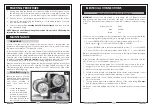
Drive Belt
(see fig. 7)
Should the lathe slow down
whilst turning, it is an indication
that the drive belt is stretched
and needs renewing, in
which case, proceed as
follows
1.
Set the variable speed
control to its highest
speed. Turn the spindle
by hand to ensure the
speed is fully engaged.
(The drive belt is easier to
remove in this position).
14
Fig. 7


