Page 33 of 41
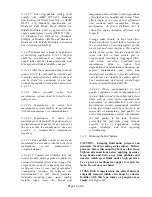
Engine speed sensor (magnetic pick-up) check
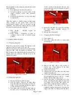
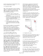
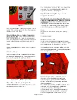
Verify wiring and connector at engine speed sensor
are secure. Magnetic pick-up is located on the right
side of the engine on the flywheel housing. (
Figure
#35
)
Figure #35
With engine running, verify that the tachometer is
functioning normally.
Refer to section 3.5.4 of Engine Operator’s Manual
to properly reposition the magnetic pick-up if
tachometer is not functioning.
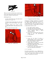
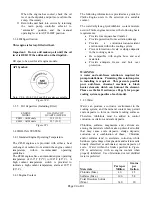
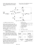
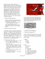
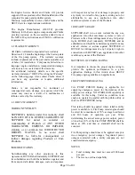
Once magnetic pick-up is repositioned: On the
Clarke instrument panel, operate the “OVERSPEED
RESET” switch for two (2) seconds and release.
(Refer to
Figure #9
).
The
“INITIALIZATION PATTERN”
will flash. This
is normal. The continuous five (5) blink flash
sequence should turn off at this point. If problem still
exists, replace engine speed sensor (magnetic pick-
up).
3.5.6 FIELD SIMULATION OF PUMP
CONTROLLER ALARMS
Field simulation of (7) pump controller alarms, refer
to document C133440 and C136197 contained within
engine documentation bag for supporting
instructions.
• Alarm 1: Over speed Shutdown: Follow
over speed verification steps per section 3.5.3.
• Alarm 2: Low Oil Pressure: With the engine
running, jumper the engine mounted low oil pressure
switch at terminal “WK” to “GROUND”.
Wait for 15 seconds and controller alarm will
activate.
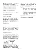
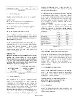
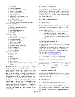
• Alarm 3: High Engine Coolant Temperature:
With the engine running, set the High Engine Coolant
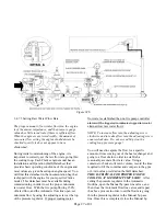
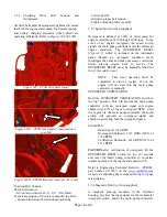
Temperature DIP switch to “ON” (see
Figure #36
).
Use a fine pick or small screwdriver and slide the
white slider to the left. Wait for 30 seconds and
controller alarm will activate. Set white DIP switch
slider to “OFF” (right) when simulation is complete.
• Alarm 4: Low Engine Coolant Temperature: With
the engine not running, set the Low Engine Coolant
Temperature DIP switch to “ON” (see
Figure #36
).
Use a fine pick or small screwdriver and slide the
white slider to the right. Controller alarm will
activate immediately. Set white DIP switch slider to
“OFF” (left) when simulation is complete.
• Alarm 5: Overcrank: Use manual stop lever (ETS
Governor Solenoid) to prevent the engine from
starting during the cycle-crank testing.
NEVER
shut
off the fuel supply to the engine to prevent it from
starting. Shutting off the fuel supply will
cause an air lock condition in the fuel system
and possibly cause fuel system component
damage.
Figure #36
Alarm 6: High Raw Water Temperature Alarm
Verification
With the engine running from the main pump
controller, jumper the two terminals of the high raw
water temperature switch. The switch is located
within the raw water plumbing in between the
cooling loop and the inlet of the heat exchanger or
charge air cooler (if equipped).
(High raw water temperature switch, set to alarm
105°F, standard) Continue jumping the circuit for 30
seconds minimum until the alarm is indicated at the
controller at interconnect terminal #310
Reset the main pump controller to reinstate normal
operation of engine and controller
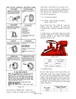
• Alarm 7: Low Raw Water Flow Alarm
Verification: Clarke engines utilize two pressure
sensors in the raw water plumbing to alarm via a Low
Flow Alarm Board a decreased flow rate condition.
One sensor is located within the cooling system

