background image


T H E   C O N T I N U O U S   P O W E R   C O M P A N Y


Page 8 

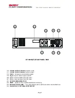
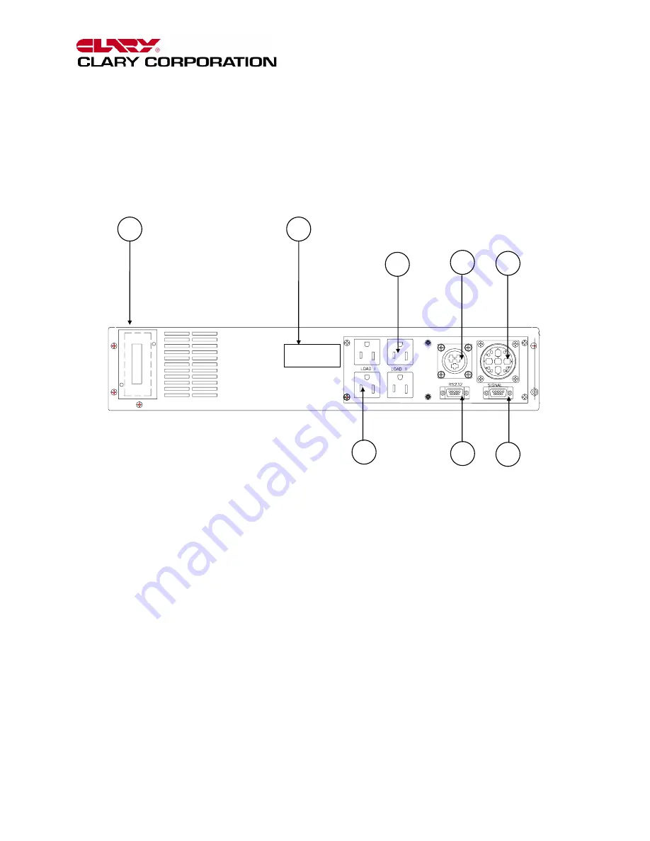
DT1000R(ET) REAR PANEL VIEW 

16  120VAC OUTPUT (LOAD II)

- System output 


17  120VAC OUTPUT (LOAD I)

- System output 


18 RS232 

- Computer communications signals 


19 Signal 

- Open-collector signal contacts 


20 AC 

In 

- Input receptacle for all AC power 


21 DC 

In 

- Input receptacle for all DC power 


23  SYSTEM GROUNDING STUD 


24 SNMP

 – (Option) Slot for sophisticated Network monitoring 

25 IDENTIFICATION 

LABEL

 – The system Model number and Serial number are identified here


26  BLANK PLATE: OPTIONAL INPUT/OUTPUT 


24 

25 

16 

20 

21 

17 

19 

18 

Summary of Contents for DT1000R

Page 1: ...s proprietary confidential and not to be disclosed disseminated or used except for the purpose provided by CLARY CORPORATION P N 510 12750 REV NR Date 2 2001 CLARY CORPORATION 1960 S Walker Avenue Mon...

Page 2: ...BLE OF CONTENTS TITLE PAGE TABLE OF CONTENTS 2 INTRODUCTION 3 TECHNICAL DESCRIPTION 4 PACKAGING 6 PHYSICAL DESCRIPTION 7 INSTALLATION 10 OPERATION 11 SIGNALS AND INTERFACING 12 SPECIFICATIONS 13 CARE...

Page 3: ...nce of the UPS and batteries Be aware of the following symbols and their meaning as they appear throughout the manual This equipment generates and uses radio frequency energy and if not installed and...

Page 4: ...the supply components that keep the entire system operational Production downtime can now be virtually eliminated by knowing exactly what patterns the supply utility power maintains and by knowing ex...

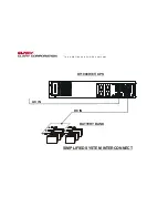
Page 5: ...T H E C O N T I N U O U S P O W E R C O M P A N Y DT1000R ET UPS BATTERY BANK SIMPLIFIED SYSTEM INTERCONNECT DC IN AC IN...

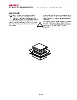
Page 6: ...there is significant damage to the carton or if there is any physical damage to this unit report this to your carrier These units are encapsulated in a protective wrap that comes apart once the produc...

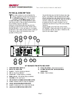
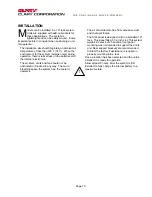
Page 7: ...witches always hold the switch in for at least two seconds to insure function confirmation This feature has been implemented into the system design to avoid inadvertent operation of any of the user av...

Page 8: ...communications signals 19 Signal Open collector signal contacts 20 AC In Input receptacle for all AC power 21 DC In Input receptacle for all DC power 23 SYSTEM GROUNDING STUD 24 SNMP Option Slot for s...

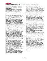
Page 9: ...cessful transition Load II A momentary push button switch that works identical to LOAD I except it corresponds to the LOAD II AC output receptacles at the panel Alarm Silent Test A momentary push butt...

Page 10: ...The air inlets vents and fan should not be obstructed or blocked in any way The more breathing space the system has the cooler it operates The air should remain free from excessive dust and chemical...

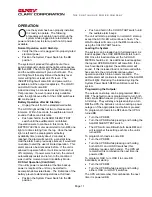
Page 11: ...Mode DC Start Operation Cold Start If no utility power is available at the time backup power is required the unit may be started to accomplish abbreviated tasks The limitations of the battery prevent...

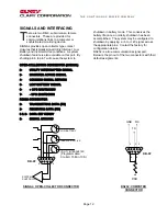
Page 12: ...tdown has been accomplished The system may be configured to shutdown by applying a 5 to 12V signal across the appropriate pins Contact the factory for configuration details RS232 is a true communicati...

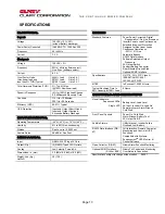
Page 13: ...8 0 457 Weight Lbs Kg HxWxD 30 13 5 DESIGN Standard Features Power Factor Corrected Digital Regenerative On Line Sinewave Inverter Powers Load Continuously Extended Brownout Protection Designed for No...

Page 14: ...en or mutilate the battery or batteries Released electrolyte is harmful to the skin and eyes It may be toxic CAUTION A battery can present a risk of electrical shock and high short circuit current The...

Page 15: ...actory In consulting the factory always have the unit model number and serial number at hand This information is located on the identification label and is essential in retrieving your unit s performa...

Page 16: ...Page 16...
Reviews: